
This page describes the Bounce ball game project, which is a part of the Embedded Systems-1 course. The aim of the project is to build a bounce ball game on the STM32L Discovery Low Power platform which uses the Cortex M3 processor.
STM32L Discovery Board Details
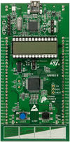
STM32L basic board
The STM32L Discovery board is a basic one in the series which use the Cortex M3. It is based on an STM32L152RBT6 and includes an ST-Link/V2 embedded debugging tool interface, an LCD (24 segments, 4 commons), LEDs, pushbuttons, a linear touch sensor or touchkeys.
The features of the board which come in handy in building this project are:
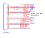
- The extension ports consisting of 4 GPIO ports, with each of the pins interfaced to the Nested Vector Interrupt Controller
- The external 3V and 5V supply pins which can be used to provide power to addon boards
- Built-in SPI and USART modules (which are in this project, not used for communication)
The programming of this board can be done on the open-source toolchain as described in the article – Getting Started with STM32L-Discovery Board, or on the evaluation version of Keil uVision platform.
Nokia LCD add-on board for STM32
The add-on board consists of the following features:
- Connector slot for Nokia LCD
- A joystick(4 direction and a push) and two push-buttons.
- MicroSD card slot
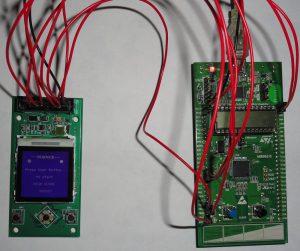
Project setup and connections
LCD controller and communication details
![]()
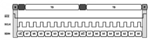
The LCD used has in-built controller of S1D15G00 series which communicates with SPI protocol, with 9 bit data width. The control command or data sent to the controller is recognized using the first bit on the line. The remaining 8 bits are received and interpreted with MSB first logic. The colour information of each pixel is sent in 12 bit format with each pair of pixels packed in 3 bytes (as shown). A software library of basic display functions can be found in the Tutorial by James Lynch. The SPI protocol can be implemented using GPIO pins, with bit-banging with appropriate timing. The conroller has a wrap-around increment logic, which can be used to adress pixels in a specific area using control word PASET and CASET, so that the whole screen need not be refreshed each time. BMP images can also be displayed if the size of the image can fit in the flash memory of the STM32L board.
As the controller uses the already described 12 bit format and byte-packing, appropriate .bmp to hex array conversion is needed before using the image in the code.
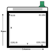
The co-ordinates of the pixels on the Nokia-6610 LCD panel which uses the above described controller, is shown in the figure. The horizontal axis increases the y co-ordinate and vertical, the x co-ordinate. Contrast of the lC can be adjusted by appropriate command to the controller which can be found in the same tutorial mentioned above, or the datasheet of the controller Bit-banging on GPIO can give a speed of 1.2 MHz max. This speed is fast enough to render frames so that the motion of an pbject looks continuous to the human eye. However, the speed is not as fast as a dedicated SPI perpheral, so that timer need not be used to give the needed delay for adjusting the frame rate. Hence, a continuous rendering of pixels has been performed, to give the motion of the ball and bat. The timing diagram of the communication link is shown in the figure.
The GPIO bit bang needs the following steps :
     1. Reset Clock pin
     2. Set Data pin high for data, and low for command
     3. Set Clock pin
     4. Reset Clock pin
     5. Put valid bit on Data pin
     6. Set Clock pin
     7. Perform last three steps a total of 8 times
Loop unrolling, and direct register write at GPIO increases the speed of communication by a large amount as this is the hotspot of the code.
Algorithm of Bounce ball
The game needs three objects
- Surrouding grid
- Ball
- Bat
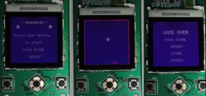
The grid is stationery, so needs to be rendered only in the beginning of each game.The bat moves on key press events. The ball moves in each frame. In order to increase speed of the application and to make responses to user-input quicker, the frames are rendered only diferentially. i.e . The pixels involved in the movement of needed object are the ones which are addressed by the code. The other pixels remain unchanged. So even though the movement occurs rapidly, the number of pixels changed in each frame, is only a small fraction of the total frame. The user buttons are mapped to interrupts which trigger bat movement.The velocity of the bat movement is fixed. Appropriate bounds on the bat position are enforced to assure that surrounding grid is not erased by the bat. The ball movement is modelled to be elastic on each wall impact, and the reflection on the bat is made a function of the impact position. The velocity of the ball is made to increase on each bounce, so that the level increases with time. A simple main-screen which shows the needed desciption and the present highscore, is displayed at the start of the application. A User Button on the STM32L board is used as a Start and Pause control for the user. On pause, the screen is frozen at the end of the frame rendered at that instant, so that the ball and bat appear complete at pause. When the ball passes over the line at the top of the bat, the game closes with a GAME OVER screen and displays the score of the game played along with the high score. High scores are stored in a non-volatile meomry (an EEPROM in the current case), so that a power-down of the board does not affect the data stored. The high score is updated only when a game score exceed the present high score. However a failure at the time when the storage of a highscore is occuring may corrupt data.
The algorithm is described in the pseudo code below:
while(1)
{
 if(start game)
 {
      initialize the game variables

      while(1)
      {
           if(not pause game)
           {
              if(key pressed)
                {
                  calculate new bat position
                  saturate bat Y position
                  render the bat differentially
                }
              calculate new ball position
              if(ball hits bat)
                {
                  saturate ball X position  // with respect to Xmax, to avoid clipping of bat
                  calculate new slope according to impact position of ball on bat
                  calculate ball Y direction according to impact position of ball on bat
                  increase ball velocity by the increment value
                }
               if(ball hits vetical grid)
                {
                  reverese ball Y direction
                }
               if(ball hits top grid)
                {
                  reverese ball X direction
                }
              round the positions to the integer
              saturate ball X position // with respect to Xmin only
              saturate ball Y position // with respect to Ymin and Ymax
              render the ball differentially
          }
      }
   }
}
Game Snapshots
Recent Comments