
Aim:
To design a Bootloader which boots the application code and updates the firmware through a
serial communication protocol.
Theory:
A boot loader is a short piece of code that may be written to execute at the start of flash
memory and serve as both an application loader and an update mechanism for programs
operating on microcontrollers. The boot loader can be designed to update the
microcontroller’s code using either the UART, SSI, I2C, CAN, Ethernet, or USB ports. To
upload the user application through the bootloader and communicate with it, we can use any
communication protocol. This idea uses UART because it is simple to create a host desktop
application that acts as a flashing facility. The boot loader can be modified by adding or
removing routines at compile time, or by changing the source code.
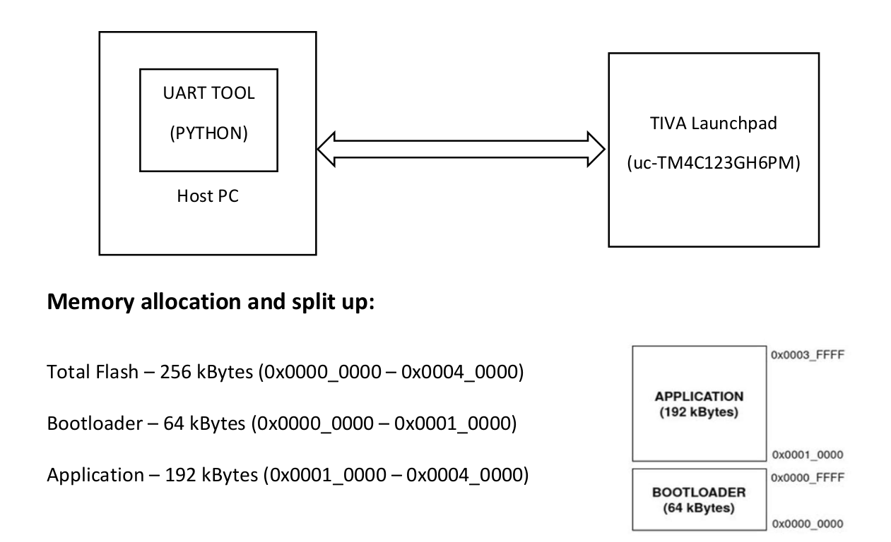
Project Setup:
TIVA board – connected to PC via UART0
Host PC – contains python UART tool running on it
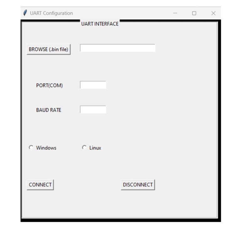
Python Tool:
Browse button – to select the binary file
Baud – to specify the baud rate (115200)
Port – to specify the port to which board is connected (COM 3)
Radio buttons (Windows (COM)).
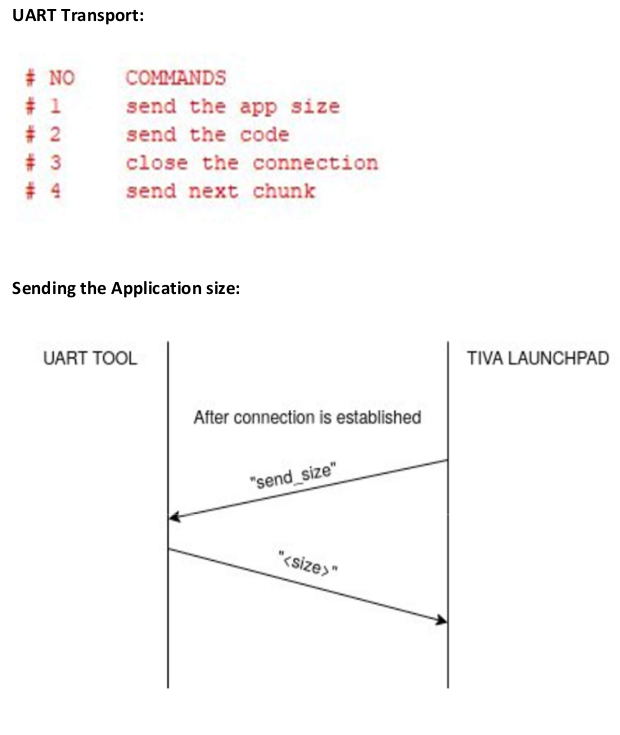
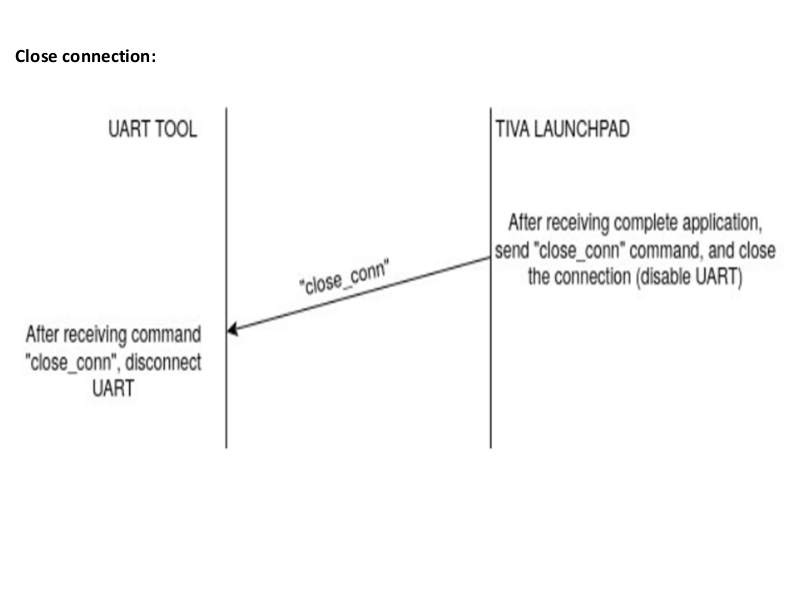
UART interface:
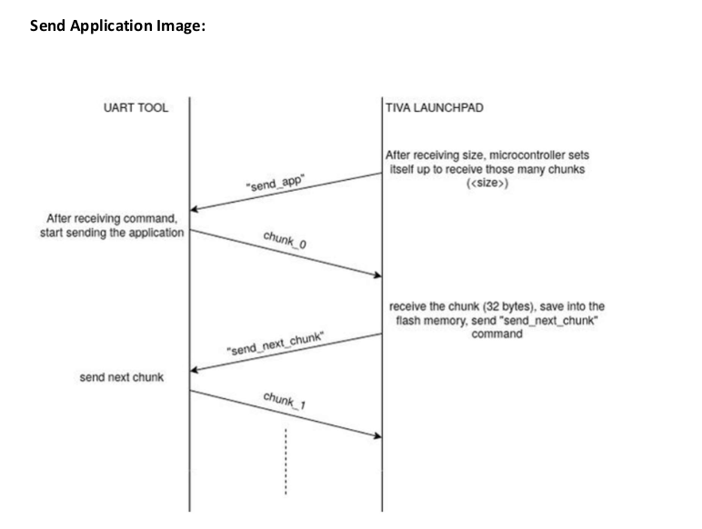
UART communication:
The UART handling functions are UART_SND() AND UART_RCV().
The connections required to use the UART port are the following two pins: U0Tx and U0Rx.
The device communicating with the boot loader is responsible for driving the U0Rx pin on
the Tiva microcontroller, while the Tiva microcontroller drives the U0Tx pin.
While the baud rate is flexible, the UART serial format is fixed at 8 data bits, no parity, and
one stop bit. The baud rate is supported by the device communicating with the boot loader.
When using a fixed baud rate, the frequency of the crystal connected to the microcontroller
must be specified. Otherwise, the boot loader will not be able to configure the UART to
operate at the requested baud rate.
Bootloader flow:
1.This project consists of
I . Boot loader code named Relaible_boot_loader.
II. A sample application code which is intended to send to the processor, named blinky.
III. Python interface code to create an interface for sending the binary application of the
app.
2.Run the python code (Written in version 3.9)
3.An UART interface will be shown.
4.Browse the application .bin file in Browse (.bin file) section.
5.Fill the Baud rate=115200 and enter port (Ex: 3, if it is COM3) as the number from the
hardware configuration settings.
6.Run Reliable_boot_loader project and you can observe the application (.bin file)
information in memory section of the CCS.
Observation:
It is observed that the communication between the UART interface and the CCS tool is
achieved using the codes provided.
The output can been seen as follows:
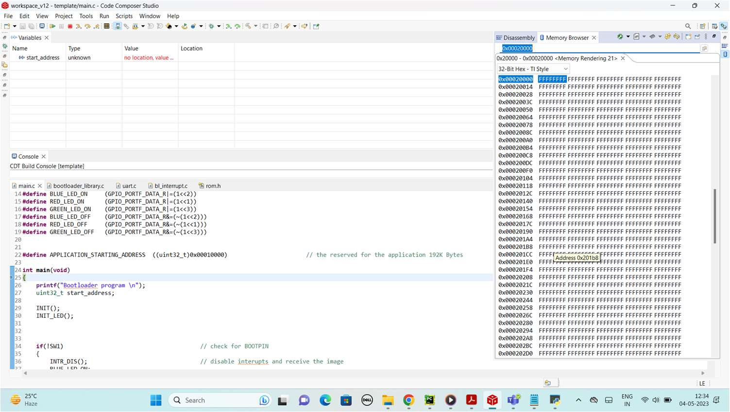
As it can be seen the value ffff at initial stage.
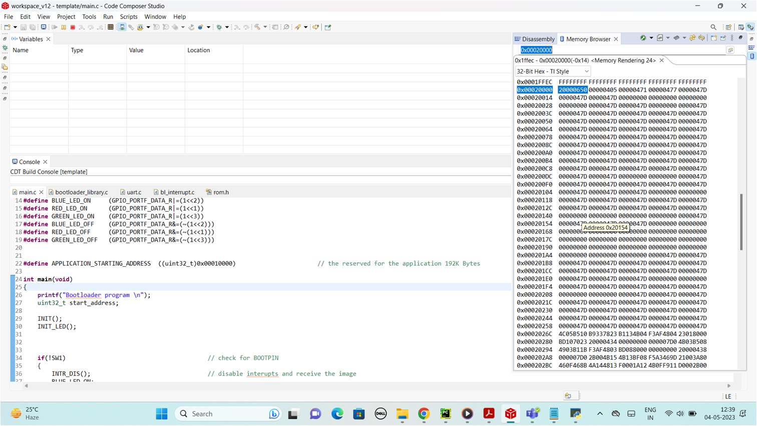
After execution of program the data can be seen in memory browser.
In the future checksum bits can be added to ensure more reliability and also the different
types of hashing algorithms can be used.
Conclusion:
Thus, a Bootloader which boots the application code and updates the firmware through a
serial communication protocol has been designed and implemented.
Code:bootloader code
Recent Comments