
PROBLEM STATEMENT:
To find the average voltage of a PWM waveform using Tiva tm4c123gh6pm microcontroller.
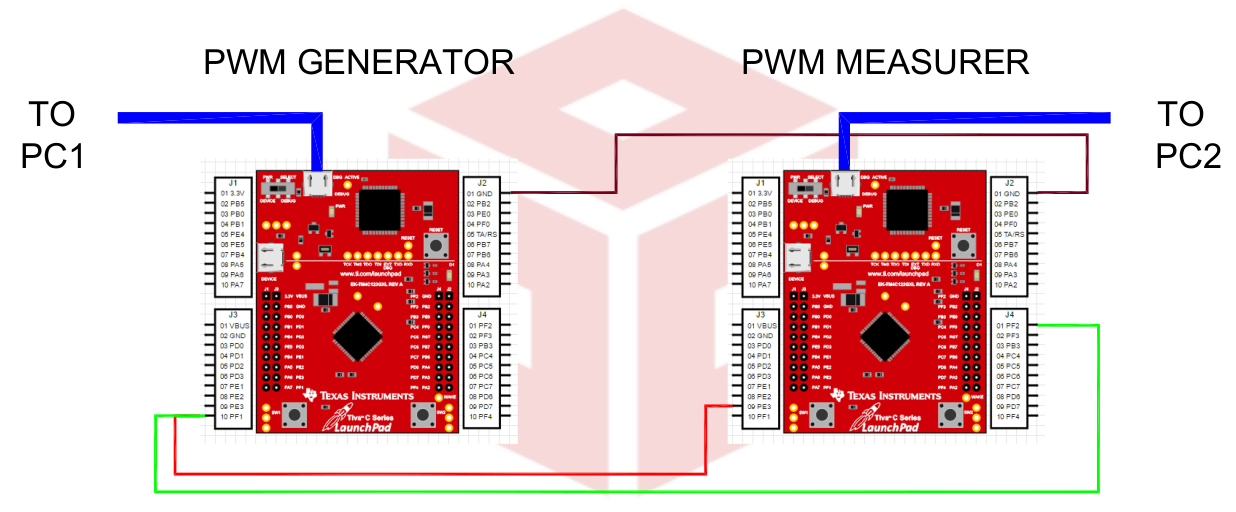
Figure: Block diagram of the setup
DESIGN APPROACH
Approach 1: Using timer peripheral
Timer 1A (pin PF2) is configured in rising/falling edge trigger mode.
The on period (Ton ) of the pulse is evaluated as the difference
between the time-stamp of a falling edge and the immediate
preceeding rising edge.
The total time period (T ) is evaluated by the timestamp of two
successive rising edges.
Assuming VDD = 3.3V , the average voltage can be calculated as

DESIGN APPROACH (CONTD.)
Approach 2: Using ADC and running average
ADC0 analog input channel on PE3 pin is used for sampling the
PWM signal.
Average of the waveform is evaluated by averaging 1e4 samples of the
digitized analog input.
The average voltage after (n + 1)th iteration is given as
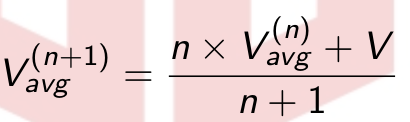
Where V is the value of the ADC at the sampling instant.
INPUTS AND OUTPUTS
PWM signals are generated using another Tiva microcontroller board.
SysTick timer and UART commands used to set the on time and off
time of the generated PWM pulses.
Results displayed on LCD screen.
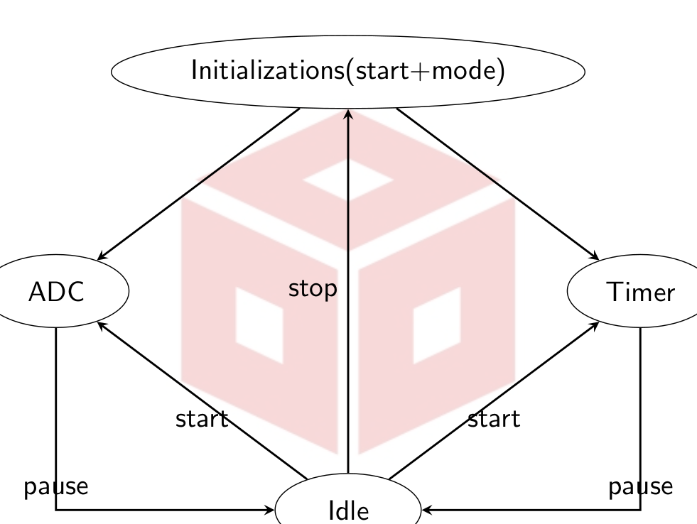
FLOWCHART
RESULTS:
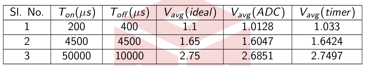
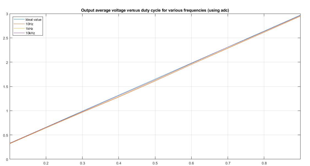
Figure: Output voltage versus duty cycle using ADC
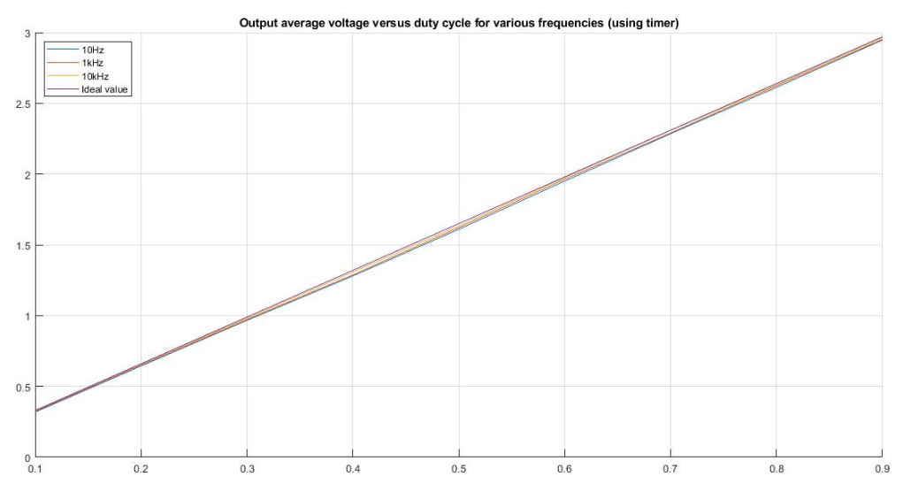
Figure: Output voltage versus duty cycle using timer
CONCLUSION:
We are able to measure average value of PWM signal using timer mode and ADC mode.
Average value of PWM signal is very accurate when measured in timer mode compared to ADC mode.
ADC mode can be used to evaluate average value of any type of signal with varying voltages.
Timer mode can work accurately for frequencies up to 50 KHz. (The operation mode used in this project offers a resolution of 1µs)
ADC mode can work accurately for high frequency up to 100 KHz.
CODE:
Recent Comments