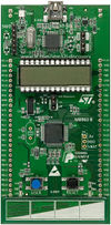
This page describes the Android Based Gesture Controlled Car Project, which is a part of the Embedded Systems-1 course. The aim of the project is to build robot car which is controlled by Gesture using a Smart phone and STM32L Discovery Low Power platform which uses the Cortex M3 processor.
Introduction
The recent smart phones are embedded with various sensor link accelerometers, gyro and magnetic sensor. These sensors can be used for translating the hand gesture to control signals for any robot. In this case we are controlling a car’s motion like speed and the direction by the gesture of the operator’s hand. Z-axis motion is used for controlling the speed and X-axis movements gives the direction of the motion for the car.
Implementation
 The implementation block shows various blocks and there connections.We have connected the smart phone through wireless network to wifi to UART convertor module (Hi –like). which further send its collected control information to STM32 board over UART port 1 then the STM 32 PWM signal for DC motors of car as per the control signal.
Components Used
The following components are required
- 1. STM32L152 Discovery Board – 1
- 2. NUXUS 5 (SMART phone) – 1
- 3. HI-LINK WIFI-UART Module – 1
- 4. Robotic Car – 1
- 5. Transistors IC7805, Resistors, LM293D-2 , 9V battery
STM32L Discovery Board Details

STM32L Board
The main features of the board which were used in this project are:
- The external 5V supply pins is connected to WIFI to UART board which provides the power to STM32 board
- two GPIO Pins(PB7 & PB8) are configured as PWM output pins given to H bridge Drive circuits for controlling DC Motors.
- two GPIO Pins(PB3 & PB5) are configured as ON/OFF output pins given to H bridge Drive circuits for controlling DC Motors.
- Built-in USART module (USATR1)(PA9 PA10) is connected to output of WIFI to UART convertors.(which is communication link for control.
The board is running very simple UART polling software which is waiting for the gesture orientation on UART port and on reception of valid information it will modified the 4 GPIO pins PWM push width resulting in motion change of the CAR.
Note:- The all four Pins can be made PWM(PB6 PB7 PB8 PB9) but due to nonfunctional pin PB6 we gone for above configuration.
SMART Phone (NUXUS 5)

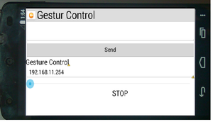
Gesture Control GUI on Nuxus5
The SMART Phone is used for the project is NUXUS5
- SMART phone is installed with Android 4.4 (kitkat).
- We are using software sensor “Orientation sensor” for translation the Gesture.(internally uses Accelerometer and magnetic sensor)
- We have developed an android application “Gesture Control” in Android using JAVA.
- The application have GUI which gives option for setting Cars IP and initial orientation of operator and START and STOP options.
- App internally runs a UDP client socket program which periodically send orientation information to Car and show the various motion information on display.(direction of motion <FORWARD , REVERS ,LEFT, RIGHT, STOP> and speed in progress bar).
WIFI to USART Convertor
The module use for translating UDP packets to USART signals is HLK-RM04
- The module is configure in default Serve mode where it sets up wifi network which needed to be join by smart phone app.
- Use a Static IP add seting “192.168.11.254” for simplicity.
- Set USART to bored rate 115200.
Note - The module sends USART Transmission to same wifi port from which it received last UDP packet so use same UDP port in App for Tx and Rx.
H bridge Drive and DC motors
LM293D H bridge Driver IC is use for controlling the DC motors speed and direction of motion. the table shows the motion with GPIO pin status
| PB3 | PB5 | PB7 | PB8 | MOTION |
|---|---|---|---|---|
| 1 | 1 | 1 | 1 | STOP |
| 1 | 1 | 0 | 0 | Foreword |
| 0 | 0 | 1 | 1 | Revers |
| 1 | 1 | 1 | 0 | Turn Left |
| 1 | 1 | 0 | 1 | Turn Right |
Future work
Various Sensor can mounted on car and they can be programed and interfaced with STM32 for sending information back to Smart phone and they operation can be control by the android app. by using lithium-ion battery we can enhance the speed and operation time of the car.

Recent Comments