
Problem Statement
To create a system for controlling(ON-OFF) the electricity supply.
Idea
Generally the load used in day to day practice are inductive, capacitive or resistive. The main problem caused by inductive loads is due to the fact that it gives a large spike due to di/dt. This can be removed by sensing zero crossing and switching off the circuit at that point of time.
Block Diagram
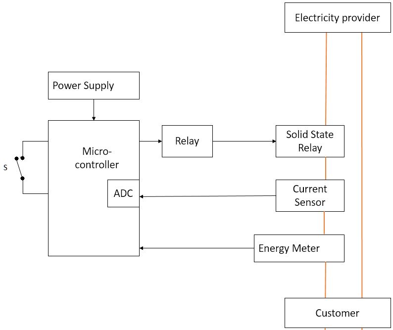
As shown in block diagram, current through main line(indicated by red color) is sensed by using current sensor. The output voltage of current sensor is proportional to the input current i.e. current through main line. Depending on the status of switch ‘S’ when zero current through main line is sensed, a signal is sent to relay and electricity supply to customer will cut-off.
Component Used and Specifications
1. TIVA 4C 123GH6PM :
2. ACS 712:
            a. Fully Integrated, Hall Effect-Based Linear Current Sensor.
            b. Sensitivity of 66mV/A.
3. 1 channel relay module:
a. 7A 250V AC
4. LM 324 :
a. Used as Amplifier.
5. JG ZG3NC (Solid State Relay):
a.16 A 90-250V AC
Softwares Used
1. Code Composer Studio
Flow of work
1. Current through main line is sensed and output voltage from current sensor is observed on CRO.
2. Analog to digital converter(ADC) of micro-controller is configured.
3. Status of switch is checked.
4. Open switch indicates not to cut electricity supply and closed switch is indication to cut electricity supply.
5. When switch is open, keep relay activated.
6. When switch is close, deactivate relay which will further deactivate solid state relay i.e. electricity supply to customer is cut-off
Recent Comments