
| INTRODUCTION | TIVAC UART | UART INT | SAMPLE | TASKS |
UART in TM4C123GH6PM Launchpad
A serial port programming is a method of transferring data serially by the means of a few wire, unlike a parallel port which requires many wires for data transfer and limited to a short distance, serial port programming can be used for transferring the data to a larger distance. The advantage of using this serial port is that it is very cheap as compare to the parallel port since it requires a single data line for data transmission making the hardware configuration easy and simple.
Serial data communication uses two methods, asynchronous and synchronous. The synchronous method transfers a block of data (characters) at a time while the asynchronous transfers a single byte at a time.
In this article we are going to use a UART module for serial port communication that uses two pins i.e. RX and TX for data transfer but before proceeding you should have the knowledge of following terms related to the UART.
Half and full-duplex transmission
In data transmission, a duplex transmission is one in which the data can be transmitted and received. This is in contrast to a simplex transmissions such as printers, in which the computer only sends data. Duplex transmissions can be half or full duplex. If data is transmitted one way at a time, it is referred to as half duplex. If the data can go both ways at the same time, it is full duplex. Of course, full duplex requires two wire conductors for the data lines (in addition to ground), one for transmission and one for reception, in order to transfer and receive data simultaneously.
Asynchronous serial communication and data framing
The data coming in at the receiving end of the data line in a serial data transfer is all 0s and 1s; it is difficult to make sense of the data unless the sender and receiver agree on a set of rules, a protocol, on how the data is packed, how many bits constitute a character, and when the data begins and ends.
Start and stop bits
Asynchronous serial data communication is widely used for character-oriented transmissions. In the asynchronous method, each character, such as ASCII characters, is packed between start and stop bits. This is called framing. The start bit is always one bit but the stop bit can be one or two bits. The start bit is always a 0 (low) and the stop bit(s) is 1 (high). For example, look at the following figure where the ASCII character “A”, binary 0100 0001, is framed between the start bit and 2 stop bits. Notice that the LSB is sent out first.
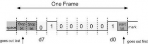
In the above figure, when there is no data transfer, the signal stays 1 (high), which is referred to as MARK. The 0 (low) is referred to as SPACE. Notice that the transmission begins with a start bit followed by D0, the LSB, then the rest of the bits until the MSB (D7), and finally, the 2 stop bits indicating the end of the character “A”.
In asynchronous serial communications, peripheral chips can be programmed for data that is 5, 6, 7, or 8 bits wide. While in older systems ASCII characters were 7-bit, the modern systems usually send non-ASCII 8-bit data. The old Baud code uses 5- or 6-bit characters but they are rarely seen these days even though most of the hardware still supporting them. In some older systems, due to the slowness of the receiving mechanical device, 2 stop bits were used to give the device sufficient time to organize itself before transmission of the next byte. However, in modern PCs the use of 1 stop bit is common. Assuming that we are transferring a text file of ASCII characters using 1 stop bit, we have a total of 10 bits for each character since 8 bits are for the ASCII code, and 1 and 2 bits are for start and stop bits, respectively. Therefore, for each 8-bit character there are an extra 2 bits, or 25% overhead. (2/8×100=25%)
Parity bit
In some systems in order to maintain data integrity, the parity bit of the character byte is included in the data frame. This means that for each character (7- or 8-bit, depending on the system) we have a single parity bit in addition to start and stop bits. The parity bit may be odd or even. In the case of an odd-parity the number of data bits, including the parity bit, has an odd number of 1s. Similarly, in an even-parity the total number of bits, including the parity bit, is even. For example, the ASCII character “A”, binary 0100 0001, has 0 for the even-parity bit. UART chips allow programming of the parity bit for odd-, even-, and no-parity options, as we will see in the next section. If a system requires the parity, the parity bit is transmitted after the MSB, and is followed by the stop bit.
Data transfer rate
The rate of data transfer in serial data communication is stated in bps (bits per second). Another widely used terminology for bps is Baud rate. However, the baud and bps rates are not necessarily equal. This is due to the fact that baud rate is defined as number of signal changes per second. In modems, it is possible for each signal to transfer multiple bits of data. As far as the conductor wire is concerned, the baud rate and bps are the same.
Baud Rate
The baud rate is defined as the rate of data transfer in serial communication, we can choose the desired baud rate for our data transmission as specified in the data sheet, later we will show you how to select this baud rate for our micro-controller.
RS232 and other serial I/O standards
To allow compatibility among data communication equipment made by various manufacturers, an interfacing standard called RS232 was set by the Electronics Industries Association (EIA) in 1960.
Today, RS232 is the most widely used serial I/O interfacing standard. However, since the standard was set long before the advent of the TTL logic family, the input and output voltage levels are not TTL compatible. In the RS232 at the receiver, a 1 is represented by –3 to –25 V, while the 0 bit is +3 to +25 V, making –3 to +3 undefined.
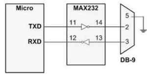
For this reason, to connect any RS232 to a TTL-level chip (microprocessor or UART) we must use voltage converters such as MAX232 or MAX233 to convert the TTL logic levels to the RS232 voltage level, and vice versa. MAX232 and MAX233 IC chips are commonly referred to as line drivers.
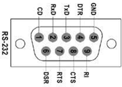
RS232 pins
The table below provides the pins and their labels for the RS232, commonly referred to as the DB-9 connector.
| Pin | Description |
|---|---|
| 1 | Data carrier detect (DCD) |
| 2 | Received data (RxD) |
| 3 | Transmitted data (TxD) |
| 4 | Data terminal ready (DTR) |
| 5 | Signal ground (GND) |
| 6 | Data set ready (DSR) |
| 7 | Request to send (RTS) |
| 8 | Clear to send (CTS) |
| 9 | Ring indicator (RI) |
Data communication classification
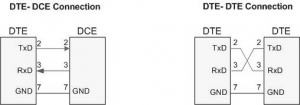
Current terminology classifies data communication equipment as DTE (data terminal equipment) or DCE (data communication equipment). DTE refers to terminals and computers that send and receive data, while DCE refers to communication equipment, such as modems, that is responsible for transferring the data. Notice that all the RS232 pin function definitions of from the above table are from the DTE point of view.
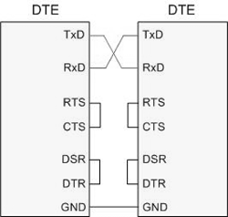
The simplest connection between two PCs (DTE and DTE) requires a minimum of three pins, TxD, RxD, and ground. Notice that the connection between two DTE devices, such as two PCs, requires pins 2 and 3 to be interchanged. In looking at the following figure, keep in mind that the RS232 signal definitions are from the point of view of DTE.
RS232 handshaking signals
To ensure fast and reliable data transmission between two devices, the data transfer must be coordinated. Some of the pins of the RS-232 are used for handshaking signals. They are described below. Due to the fact that in serial data communication the receiving device may have no room for the data there must be a way to inform the sender to stop sending data. So some of these handshaking lines may be used for flow control tool
- DTR (data terminal ready)
- When the terminal (or a PC COM port) is turned on, after going through a self-test, it sends out signal DTR to indicate that it is ready for communication. If there is something wrong with the COM port, this signal will not be activated. This is an active-low signal and can be used to inform the modem that the computer is alive and kicking. This is an output pin from DTE (PC COM port) and an input to the modem.
- DSR (data set ready)
- When a DCE (modem) is turned on and has gone through the self-test, it asserts DSR to indicate that it is ready to communicate. Therefore, it is an output from the modem (DCE) and an input to the PC (DTE). This is an active-low signal. If for any reason the modem cannot make a connection to the telephone, this signal remains inactive, indicating to the PC (or terminal) that it cannot accept or send data.
- RTS (request to send)
- When the DTE device (such as a PC) has a byte to transmit, it asserts RTS to signal the modem that it has a byte of data to transmit. RTS is an active-low output from the DTE and an input to the modem.
- CTS (clear to send)
- In response to RTS, when the modem has room for storing the data it is to receive, it sends out signal CTS to the DTE (PC) to indicate that it can receive the data now. This input signal to the DTE is used by the DTE to start transmission.
- CD (carrier detect, or DCD, data carrier detect)
- The modem asserts signal DCD to inform the DTE (PC) that a valid carrier has been detected and that contact between it and the other modem is established. Therefore, DCD is an output from the modem and an input to the PC (DTE).
- RI (ring indicator)
- An output from the modem (DCE) and an input to a PC (DTE) indicates that the telephone is ringing. It goes on and off in synchronization with the ringing sound. Of the six handshake signals, this is the least often used, due to the fact that modems take care of answering the phone. However, if in a given system the PC is in charge of answering the phone, this signal can be used.
From the above description, PC and modem communication can be summarized as follows:
While signals DTR and DSR are used by the PC and modem, respectively, to indicate that they are alive and well, it is RTS and CTS that actually control the flow of data. When the PC wants to send data it asserts RTS, and in response, if the modem is ready (has room) to accept the data, it sends back CTS. If, for lack of room, the modem does not activate CTS, the PC will deassert DTR and try again. RTS and CTS are also referred to as hardware control flow signals.
Recent Comments