
Introduction:
In this concept, an enemy is identified on a distant mountain, while our army units are stationed at an observation post. Upon detection, the enemy’s coordinates are relayed to ground control. In response, three robotic guns autonomously reposition and align in a precise formation. These swarm bots self-organize and target the enemy using laser alignment, simulating a synchronized robotic strike. The simulation focuses on visualizing a coordinated attack using swarm robotics and laser-based targeting systems.
Objective: To demonstrate the simulation of a strategic and synchronized robotic strike using autonomous swarm bots.
Motivation:
In modern warfare and defense systems, precision, speed, and coordination are critical. This simulation is inspired by a scenario where an enemy is located on a distant mountain, while our army units are stationed at an observation point. Upon identifying the threat, the enemy’s coordinates are transmitted to ground control. In response, three robotic guns—functioning as swarm bots—autonomously reposition and form an aligned formation. These bots use laser-based targeting to simulate a precise and synchronized strike. This concept emphasizes the potential of swarm robotics in military applications, showcasing autonomous coordination, rapid response, and simulated laser engagement as a safe yet effective training or tactical planning tool.
Project Objectives:
The primary goal of this project is to develop a coordinated multi-robot system capable of simulating a
synchronized laser strike. The key objectives include:
•Design and Implementation of a 3-Robot Coordination System: Develop a control architecture that enables three robotic units to act in unison, aligning and targeting based on received coordinates.
•Communication Framework:
PC to ESP Modules via Wi-Fi: Enable centralized control from a PC to all robotic units using Wi-Fi-enabled ESP modules.
Intra-Bot Communication (TIVA to ESP via UART): Establish reliable serial
communication within each robot, connecting the TIVA microcontroller with its corresponding ESP module.
Servo-Based Laser Elevation Control: Integrate servo motors to dynamically adjust the elevation of laser pointers, allowing each robot to accurately target based on the received positional data.
System Design Plan:
The coordinated robotic strike simulation relies on a modular and distributed design involving multiple subsystems working in unison. The major components of the system are outlined as follows:
Controllers:
Each robotic unit is equipped with a dual-controller setup:
Tiva C LaunchPad serves as the central control unit for motion, orientation, and actuation logic.
ESP32 handles Wi-Fi-based communication with the central PC, receiving coordinate data and forwarding it to the Tiva controller.
Localization:
An Inertial Measurement Unit (IMU) provides real-time orientation data to ensure
accurate alignment.
Wheel encoders deliver speed and displacement feedback for precise navigation and
positioning.
Actuation:
DC motors are used for mobility, allowing the bots to reposition themselves.
A servo-mounted laser pointer enables elevation control for targeting, simulating the aiming mechanism.
Power Supply:
Each unit is powered by a 18650 Li-ion battery, with a 5V regulated power supply to safely drive all electronics and actuators.
This modular design ensures autonomy, synchronization, and effective communication between all units, making the system scalable and efficient.
Coordinated Robotic Gun Formation System:
The system is designed to simulate a cooperative robotic strike, where multiple bots operate in formation based on commands from a centralized PC controller. The key aspects of the system are:
Central Control (PC Unit): The PC functions as the central command unit, responsible for:
Sending target coordinates and desired orientation to all bots.
Managing and controlling formation patterns such as V-shape or linear alignment.
Receiving status updates and feedback from each bot to monitor progress and system health.
Bot Feedback Mechanism:
Each robotic unit is equipped with:
Motor encoders for tracking movement and confirming distance covered.
An MPU-9150 IMU for capturing orientation and alignment data.
Bots continuously send “Reached” and “Clearance” updates back to the PC, indicating successful navigation and readiness.
Laser Firing Sequence:
Once all bots are in position:
The PC sends a command to trigger servo-based alignment of the laser.
After alignment, each bot fires its laser, simulating a synchronized strike.
SOS Handling and Prioritization:
If a bot encounters an issue, it sends an SOS message to the PC.
Other bots, upon receiving SOS status, reprioritize their paths and navigate to assist or adapt the formation accordingly.
This robust coordination protocol ensures both offensive precision and fault tolerance, allowing the swarm to function adaptively even in the face of individual unit failures.
Component Summary (Per Bot Unit):
Each robotic unit in the system is equipped with the following components to ensure autonomous mobility, communication, targeting, and power management:
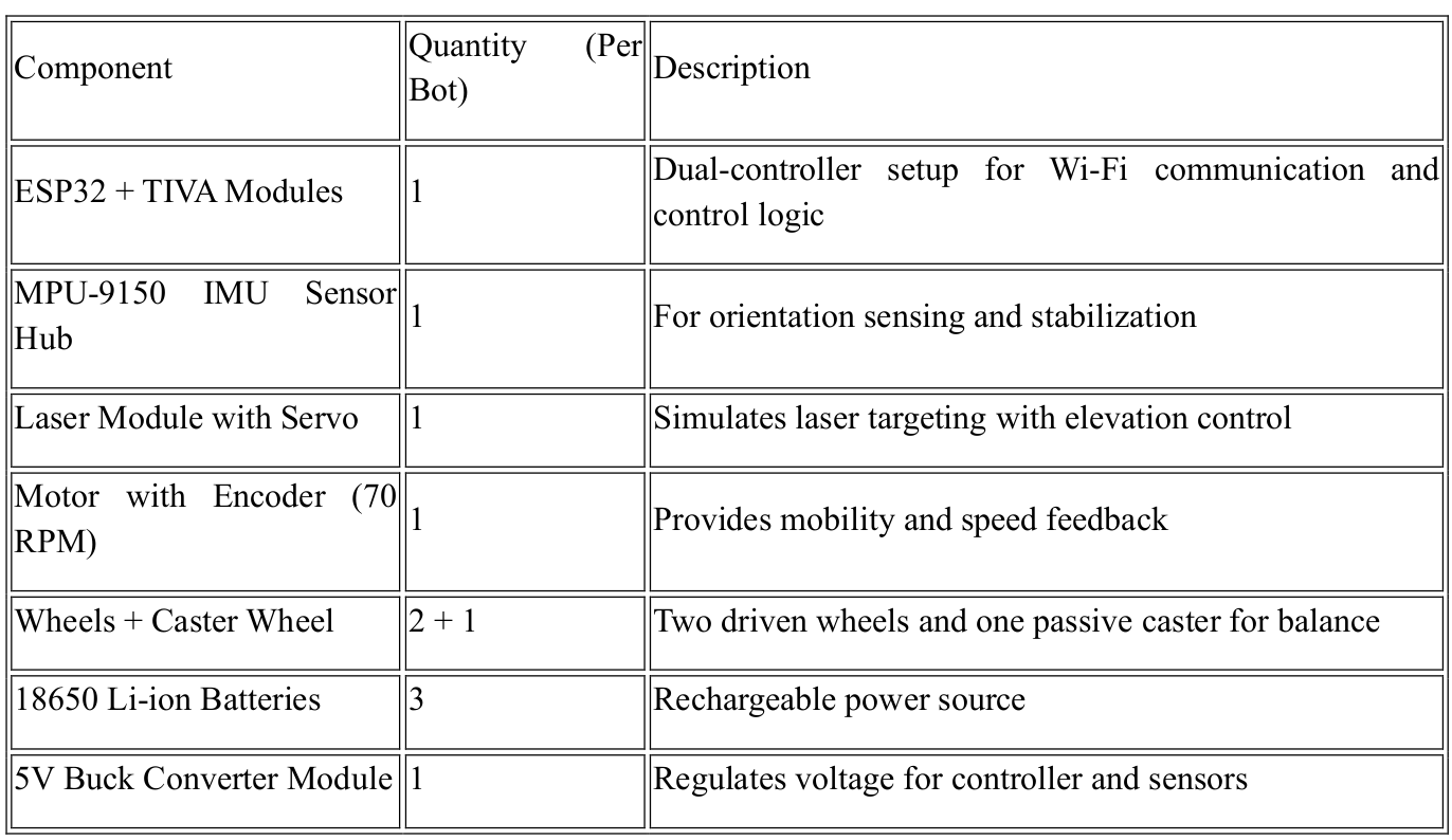
This component set ensures that each bot operates independently while remaining fully synchronized as part of the swarm formation.
Interface and Pin Planning (Tiva C LaunchPad):
The following table outlines the pin assignments for each interface used in the robotic unit, with clear mappings of peripherals to GPIO pins on the Tiva C LaunchPad:
Peripheral Interfaces and Assigned Pins:
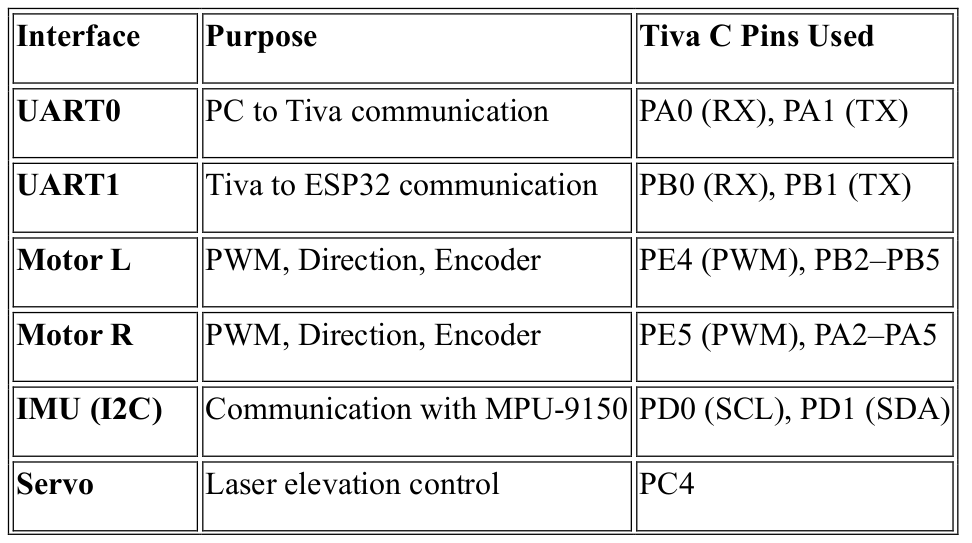
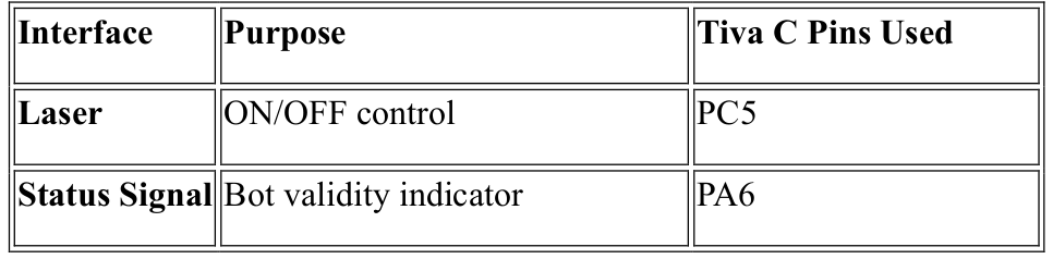
This pin mapping ensures organized hardware integration for all essential functions like communication, motion control, sensor interfacing, and targeting.
Message Types Overview:
To ensure reliable and efficient communication between the PC and all robotic units, the system employs a structured messaging protocol with fixed byte positions. This format guarantees consistency, simplifies parsing, and is optimized for embedded systems with limited processing and memory resources.
Standardized Message Structure:
Each message begins with three essential fields:
Message Type: Identifies the command or data category.
Source ID: Specifies the sender (PC or specific bot).
Destination ID: Indicates the intended recipient.
Data Payload (Bytes 4–12):
The content in these bytes varies depending on the message type and may include:
Target coordinates (X, Y, Z)
Orientation angles
Laser ON/OFF status
Speed or motion data
Servo alignment angles
Unique Message IDs (1–13):
Every command or event type is assigned a unique ID, allowing differentiation between actions such as:
Movement instructions
Servo control
Laser activation
Status or feedback messages
Design Considerations:
Optimized for low bandwidth wireless communication.
Easy to encode and decode on microcontrollers.
Ensures deterministic behavior across all nodes in the system.
This structured approach enables seamless coordination in real time, with minimal processing overhead, even in constrained embedded environments.
Message Types – BOT to PC :
The following table summarizes the structured messages sent by each bot to the central PC. Each message follows a consistent format and includes relevant data depending on the message type.
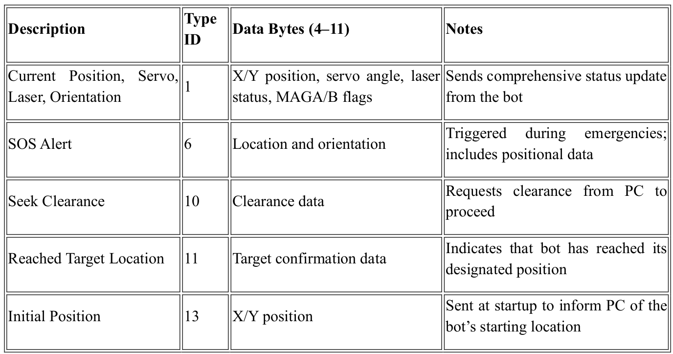
All messages include Message Type, Source ID, and Destination ID in the first three bytes for uniform parsing and routing.
Message Types – PC to BOT :
The following table summarizes the structured messages sent from the central PC to the robotic units. These messages control various aspects of bot behavior, including movement, laser operations, and power modes.
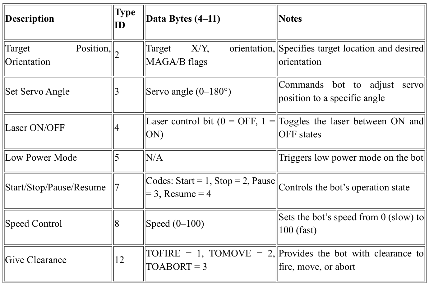
As with messages sent from the bots, all messages include Message Type, Source ID, and Destination ID in the first three bytes to ensure proper routing and interpretation.
Design Architecture :
Laser and Servo Control System :
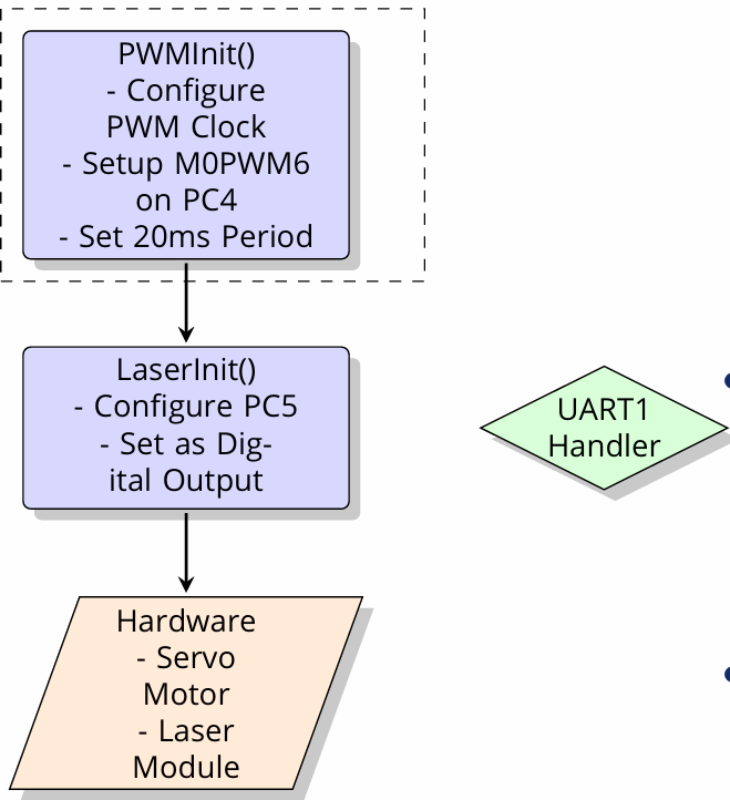
The Laser and Servo Control System is responsible for positioning the servo motor for laser alignment and controlling the laser’s activation during targeting operations. The system consists of two primary
components: the Servo Motor and the Laser Module, both interfaced with the Tiva C LaunchPad.
PWM Initialization and Configuration :
PWMInit()
Configures the M0PWM6 module on PC4 to generate a 50Hz PWM signal, setting a 20ms period for servo control.
The PWM signal is used to control the servo’s position by adjusting its pulse width within a range of 1 to 2ms, corresponding to a 0° to 180° range.
Servo Control:
The servo motor positioning is controlled via the PWM signal output through PC4(M0PWM6).
The pulse width varies from 1ms (for 0° position) to 2ms (for 180° position) to achieve precise servo alignment.
The position is adjusted by modifying the PWM03CMPAR register.
Laser Control :
LaserInit():
Configures PC5 as a digital output pin to control the laser module.
The laser is turned ON or OFF through simple GPIO control via a high or low signal on PC5.
Laser control is activated during the targeting operations to simulate the robotic strike.
Integration with Other Systems:
The Laser and Servo Control System integrates with the position tracking system to align the laser precisely based on the bot’s coordinates and orientation.
The SysTick timer ensures precise timing for laser firing and servo adjustments, ensuring the bot remains synchronized with the overall control system.
This system enables precise alignment and activation of the laser during the simulation of a coordinated robotic strike.
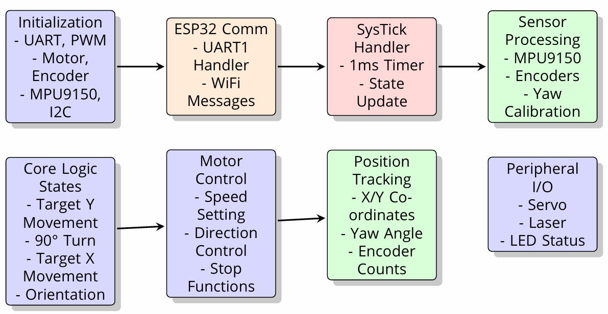
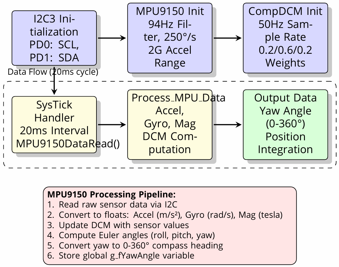
MPU9150 Inertial Navigation System :
Motor Control System: Key Functions
The Motor Control System enables the precise movement of the robotic units, managing both motor speed and direction through feedback from encoders. The system also includes testing and debugging functions for effective operation and maintenance.
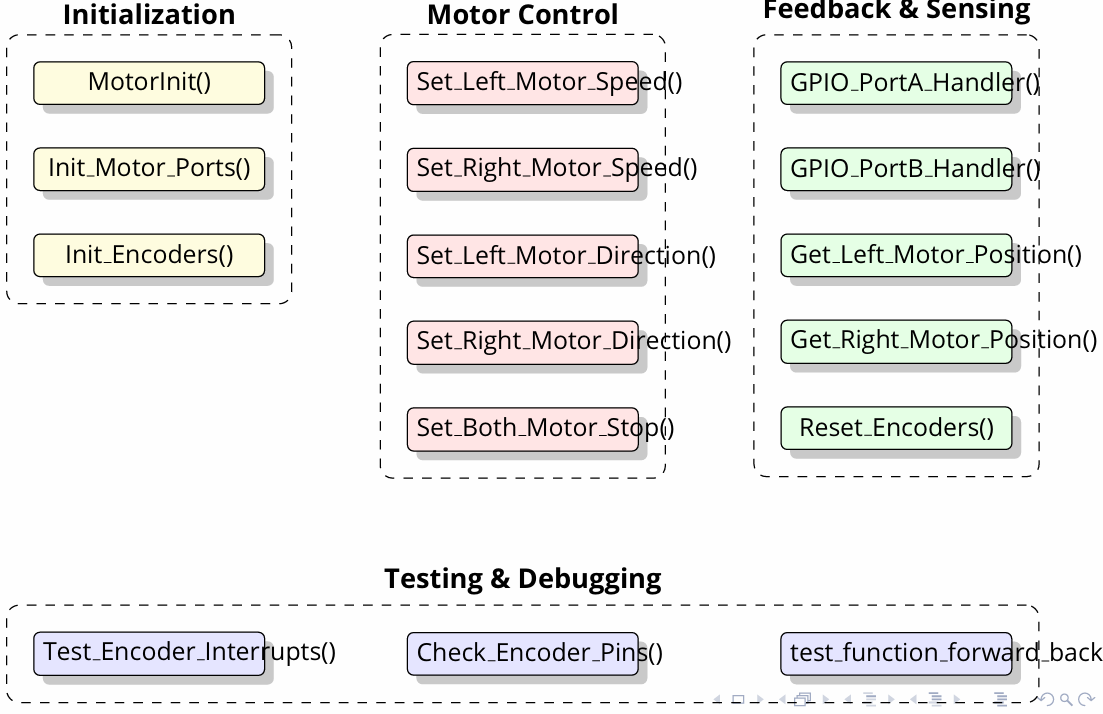
Initialization:
MotorInit():
initializes the motor control system, preparing all necessary resources for the operation of both motors.
Init Motor Ports():
Configures the appropriate GPIO ports on the Tiva C LaunchPad to control the motor drivers(PWM signals, direction control).
Init Encoders():
Sets up the encoders to track the rotational movement of the motors, providing feedback on position and speed.
Motor Control:
Set Left Motor Speed():
Controls the speed of the left motor by adjusting the PWM signal on the corresponding control pin.
Set Right Motor Speed():
Similarly, adjusts the speed of the right motor by modifying its PWM signal.
Set Left Motor Direction():
Configures the direction of the left motor, controlling whether it moves forward or backward(using a GPIO pin to set direction).
Set Right Motor Direction():
Adjusts the direction of the right motor similarly.
Set Both Motors Stop():
Stops both motors by setting their control signals to a neutral state, effectively halting movement.
Feedback & Sensing:
GPIO PortA Handler():
Handles interrupt-driven feedback from motor control signals on PortA, monitoring changes in the motor’s status.
GPIO PortB Handler():
Similar to PortA, handles feedback on PortB related to motor feedback, such as encoder pulse signals.
Get Left Motor Position():
Reads the position of the left motor from the encoder data to determine the displacement or distance traveled.
Get Right Motor Position():
Similarly, reads the right motor’s position from its encoder data.
Reset Encoders():
Resets the encoder counters to zero, often used to reinitialize motor position tracking.
Testing & Debugging:
Test Encoder Interrupts():
Tests the interrupt functionality of the encoders to ensure they correctly respond to changes in motor position.
Check Encoder Pins():
Verifies the status of encoder signal pins to ensure proper operation and data collection from the encoders.
Team Embedded (Embedded Systems Project):
A test function is included to evaluate basic motor functions, such as moving the robot forward and backward, ensuring the system operates as expected. This Motor Control System is integral to enabling precise movement and feedback in the robotic system, with testing features that ensure the motors and encoders function correctly.
Navigation State Machine :
The Navigation State Machine is designed to manage the robot’s motion through various stages, from reaching the target location to fine-tuning its orientation. It operates through a series of states with specific control parameters and feedback mechanisms.
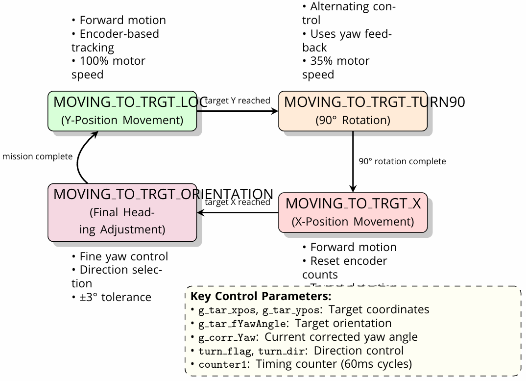
State Breakdown and Motion Phases
1. MOVING TO TARGET LOCATION (Forward Motion):
Encoder-based tracking: Utilizes encoder feedback to measure the robot’s movement toward the target.
Speed: Motors run at 100% speed.
Condition: The system continuously moves forward until the target Y position is reached.
2. MOVING TO TARGET TURN 90° (Y-Position Movement):
Alternating control: The robot switches to a rotation phase, adjusting its heading using yaw feedback.
Speed: The motors run at 35% speed to control the turn.
Condition: The robot adjusts its orientation by rotating 90° to align with the final heading.
Once the rotation is complete, the system moves to the next stage.
3. MOVING TO TARGET ORIENTATION (Final Heading Adjustment):
Fine yaw control: At this stage, the robot fine-tunes its orientation with ±3° tolerance for accurate positioning.
Direction selection: The system adjusts the robot’s direction based on corrected yaw and selected control flags.
Condition: Once the robot reaches the desired orientation, it moves toward the target X location.
4. MOVING TO TARGET X (X-Position Movement):
Forward motion: The robot moves forward along the X-axis.
Encoder reset: Encoder counts are reset for tracking the new movement along the X direction.
Condition: The robot continues until it reaches the target X position.
Key Control Parameters:
Target Detection:
Target Coordinates (x_pos, y_pos): Coordinates of the destination target.
Target Orientation (fYawAngle): The desired heading for the robot.
Yaw: The current yaw angle of the robot, corrected based on sensor feedback.
Yaw Correction: Adjustments made to align the robot’s orientation with the target.
Direction Control:
Turn Direction (turn_dir): The direction in which the robot must turn (left or right).
Timing Counter:
counter1: A timing counter operating in 60ms cycles to manage control timing and
coordination of actions.
This state machine allows the robot to navigate precisely to its target by combining position tracking,
orientation control, and adaptive speed adjustments. It integrates encoder data and yaw feedback for
accurate motion execution and orientation correction.
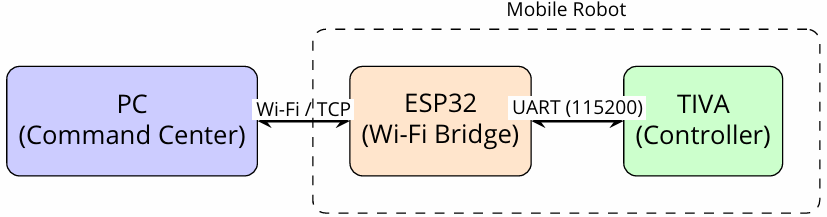
ESP32-Based Communication Gateway :
The ESP32-based Communication Gateway serves as the bridge for communication between the central PC and the robotic units. It uses WiFi UDP communication to handle commands and telemetry efficiently,
routing packets between the PC and the Tiva MCU.
Communication Overview
WiFi UDP Communication:
The ESP32 connects to the central PC at IP address 192.168.0.109 on port 5001 for incoming commands.
The local listening port on the ESP32 is set to 4210 for receiving commands from the PC.
UART Interface (UART2):
GPIO16 (RX) and GPIO17 (TX) are used for the UART interface, facilitating communication between the ESP32 and the Tiva MCU. Frame Routing
•WiFi → UART: Commands received over WiFi are forwarded to the Tiva MCU via the UART interface. These commands may include target positions, motor controls, or other system operations.
•UART → WiFi: Telemetry and status updates from the robotic units are sent back to the PC or other communication between the ESP32 and the Tiva MCU.
Frame Routing:
•WiFi → UART: Commands received over WiFi are forwarded to the Tiva MCU via the UART interface. These commands may include target positions, motor controls, or other system operations.
•UART → WiFi: Telemetry and status updates from the robotic units are sent back to the PC or other peers over WiFi. These include position, orientation, or error messages.
Frame Format:
The communication between the ESP32 and the PC follows a specific frame format:
Payload: 12-byte payload that contains the core data such as position, speed, or other commands.
Total Frame Size: The frame is a 50-byte binary frame that includes additional metadata for routing and error handling.
Destination ID (dst_id): If the dst_id is set to 255, the message is broadcasted to all devices, enabling communication with multiple bots simultaneously.
This communication gateway is crucial for ensuring seamless data transfer between the PC and the robotic units, allowing the system to operate with precise coordination and control.
GUI Features and Architecture :
The Graphical User Interface (GUI) is built using Python and Tkinter, providing an intuitive platform to control and monitor the ESP32 bots via UDP communication. The interface allows users to interact with
the system, send commands, track bot positions, and control laser firing. The architecture is designed to be user-friendly, with various tabs and features that facilitate seamless interaction.
Platform:
Python + Tkinter:
The GUI is implemented using Python for its ease of use and flexibility, with Tkinter providing the framework for building the interface.
The GUI communicates with the bots through UDP messages, sending commands and receiving telemetry data.
Tabbed Interface:
The GUI is divided into several tabs, each with a specific function
1. Control & Map Tab:
Allows the user to send commands to the bots.
Set target coordinates and view bot positions on a map.
Displays a visual representation of the bot’s current location and orientation.
2. Message Log Tab:
Logs all PC ↔ Bot communications.
The log shows parsed fields for easy readability, making it easier to track command exchanges and statuses.
3. Raw Data Tab:
Displays the raw incoming/outgoing UDP packets in hexadecimal format.
Useful for debugging and analyzing the communication packets, especially the 12-byte frames sent between the PC and the bots.
4. Firing Control Tab:
Manages the laser firing sequence.
Alternates firing between bots and plays a siren sound when the laser is activated.
Controls laser ON/OFF state via the interface.
5. Visual Grid Tab:
Displays bots with directional arrows indicating their heading and movement.
Updates blinking indicators for real-time status, including movement or targeting updates.
Message Types:
The GUI handles various message types and their corresponding controls:
Target (2): Sends target position and orientation.
Laser (4): Controls laser ON/OFF states.
Servo (3): Adjusts the servo motor angles.
SOS (6): Handles emergency situations where one bot requires assistance.
Speed (8): Sets motor speed for the bots.
Clearance (12): Handles clearance requests and responses during operations.
Target Markers:
Target Markers are drawn on the map, showing the bot’s current position and heading.
The heading arrow per bot dynamically updates to reflect the bot’s current orientation, ensuring that the user has real-time visibility of the robot’s status.
This GUI provides a comprehensive interface for monitoring and controlling the robotic system, making it easy to interact with and track the status of each bot.
GUI Backend Logic and Packet Handling :
The backend logic of the GUI is designed to handle communication with the robotic units, process incoming and outgoing packets, and trigger alerts or actions based on certain conditions. It leverages UDP
communication, packet handling, and automation features to ensure smooth operation and real-time updates.
Network Communication
1. UDP Listener Thread:
The GUI employs a UDP listener thread to receive messages from the robotic units.
The listener uses the select method to monitor and handle multiple communication sockets efficiently.
The queue is used for thread-safe handling of incoming and outgoing UDP packets, ensuring smooth data flow between the PC and the robots.
2. Outgoing UDP Packets:
Outgoing messages are formatted into 50-byte frames, which include the 12-byte payload and necessary metadata.
These packets are sent to the appropriate bot or broadcasted to multiple units based on the destination ID (dst_id).
Automation and Alerts:
1. Seek Ack:
When the Seek Ack command is triggered, it automatically requests clearance (MOVE) to proceed with the next action. This helps maintain smooth coordination between multiple bots.
2. SOS Packet:
An SOS packet triggers an alarm on the GUI.
The map blinks to visually alert the user of an emergency situation.
The target location is broadcasted to all bots, allowing them to assist the affected bot.
3. Visual and Audible Alerts:
The system plays audible alerts using the system bell or winsound (on Windows).
Visual cues such as blinking map updates or highlighted status indicators help ensure immediate attention to critical events.
Firing Control:
1. Laser Control:
The laser is cycled ON/OFF across the bots, with a delay between each cycle to simulate coordinated firing.
A siren loop is played during the laser firing sequence, adding a sound effect for realism.
2. Individual Laser OFF and Job Canceling:
If the firing operation is stopped, the laser is turned OFF for all bots involved.
The system can also cancel any ongoing job or operation, returning the robots to their idle state.
Live Updating
1. Bot Position and Heading Updates:
The positions and headings of all robots are updated every 100 ms to provide real-time tracking on the map.
The after() method is used in Tkinter to repeatedly trigger updates at fixed intervals, ensuring smooth and frequent updates without freezing the interface.
This backend logic ensures that the GUI stays responsive, provides real-time information, and can handle
automated tasks and alerts effectively, all while managing UDP communication with minimal latency.
Conclusions & Future Scope :
Project Achievements:
This project has made significant progress in designing and testing a coordinated robotic gun formation system with the following key achievements:
1. Successful Testing of 2 Robots:
Two robots have been successfully tested and integrated into the system, confirming the functionality of key features such as motion control, laser targeting, and communication.
2. Third Robot Hardware Interface:
The hardware interface for the third robot is still being debugged, but progress is being made to integrate it into the system.
3. Multi-Layered Communication Architecture:
A robust multi-layered communication architecture has been implemented, involving WiFi and UART to ensure reliable communication between the central PC and the robotic units.
4. SOS Feature:
The SOS feature allows the system to automatically reallocate robots in emergency situations, ensuring continuous operation even when one bot encounters issues.
5. Precision Laser Targeting:
The laser targeting system is highly precise, utilizing a servo-based elevation control for accurate aiming.
6. Integrated Feedback System:
Feedback is integrated from encoders and IMU sensors, providing real-time data for position tracking and ensuring accurate movement and targeting.
Future Scope:
While significant progress has been made, there are several potential areas for enhancement and future development:
1. Security Enhancements:
Future work will include implementing security mechanisms to ensure safe communication between the TIVA UART and WiFi interfaces, protecting against potential vulnerabilities.
2. Low-Power Operation:
Low-power operation will be explored to extend the robots’ operational time in the field, making them more efficient and suitable for long-duration missions.
3. Fault Isolation and Recovery:
Fault isolation and recovery mechanisms will be developed to help the system recover gracefully from failures or errors, minimizing downtime and ensuring reliability in critical situations.
4. Watchdog Timer Implementation:
The Watchdog Timer will be implemented to monitor and reset the system in case of a failure, ensuring that the robotic units remain operational even if they encounter unexpected issues.
5. Camera-Based Feedback for Enhanced Localization:
Camera-based feedback will be integrated into the system for improved localization, enhancing the bots’ ability to navigate complex environments and interact with dynamic targets.
6. Scalable Architecture for Larger Swarm Deployments:
The architecture will be made scalable, enabling the deployment of larger swarms of robots, which can communicate and coordinate in a highly synchronized manner for more complex missions.
Recent Comments