
Switch Inputs and LED Outputs
There are four ways to interface a switch to the microcontroller as shown in the following Figure:
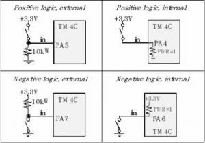
We can use either positive or negative logic, and we can use an external resistor or select an internal resistor. Notice the positive logic circuit with external resistor is essentially the same as the positive logic circuit with internal resistance; the difference lies with whether the pull-down resistor is connected externally as a 10 kΩ resistor or internally by setting the corresponding PDR bit during software initialization.
SW1 and SW2 on LaunchPad
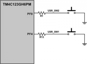
- SW1 push-button switch is connected to PF0 pin.
- SW2 push-button switch is connected to PF4 pin.
- There is no pull-up resistor connected to SW1 & SW2
- To use the SW1 and SW2, we need to enable the internal pull-up resistor for PF0 and PF4 pins.
Read SW1 & Display it on the Green LED
To read SW1 and display it on the green LED, the following steps must be taken.
- Enable the clock to PortF
- Set the Direction register PF4 as input, and PF3 as output
- Enable the digital I/O feature of PortF
- Enable the pull up resistor option in PUR register since the switch circuit does not have pull-up resistor
- Read SW1 on PortF
- Invert the value since the switch is active low and the LED is active high
- Shift right the switch bit (PF4) to green LED bit(PF3) of the value
- Write the value to green LED of PortF
- Repeat steps 5 to 8
Source Code
-
/* Read a switch and write it to the LED */ -
/* This program reads SW1 of Tiva LaunchPad and writes the inverse of the value to the green -
LED. SW1 is low when pressed (Normally High). LED is ON when high. -
*/ -
#include <stdint.h> -
#include "inc/tm4c123gh6pm.h" -
int main(void)
-
{ -
unsigned int value;
-
SYSCTL_RCGC2_R |= 0x00000020;; /* enable clock to GPIOF */
-
GPIO_PORTF_DIR_R = 0x08; /* set PORTF3 pin as output (LED) pin */
-
/* and PORTF4 as input, SW1 is on PORTF4 */ -
GPIO_PORTF_DEN_R = 0x18; /* set PORTF pins 4-3 as digital pins */
-
GPIO_PORTF_PUR_R = 0x10; /* enable pull up for pin 4 */
-
While(1) {
-
value = GPIO_PORTF_DATA_R; /* read data from PORTF */
-
value = ~value; /* switch is low active; LED is high active */
-
value = value >> 1; /* shift it right to display on green LED */
-
GPIO_PORTF_DATA_R = value; /* put it on the green LED */
-
} -
}
Read SW2 and Write it on Red LED
To read SW2 and display it on the Red LED, the program is similar to the previous program except extra steps needed to take care of PortF0 as described below:
- The SW2 is connected to PortF0 pin, which is shared with NMI (non-maskable interrupt).
- To prevent accidental write to configuration registers and thus disables NMI, the configuration register bits for PortF0 are normally locked.
- They may be unlocked by writing a pass code value of 0x4C4F434B to the LOCK Register followed by setting bit 0 of the Commit Register (GPIOCR).
Source Code
-
/* Read a switch and write it to the LED */ -
/* This program reads SW2 of Tiva LaunchPad and write the inverse of the value to the red LED. -
SW2 is low when pressed. LED is on when high. */ -
/* SW2 is connected to PORTF0, which is an NMI pin. */ -
/* In order to use this pin for any function other than NMI, the pin needs be unlocked first. */ -
#include <stdint.h> -
#include "inc/tm4c123gh6pm.h" -
int main(void)
-
{ -
unsigned int value;
-
SYSCTL_RCGC2_R |= 0x00000020; /* enable clock to GPIOF */
-
GPIO_PORTF_LOCK_R = 0x4C4F434B; /* unlock commit register */
-
GPIO_PORTF_CR_R = 0x01; /* make PORTF0 configurable */
-
GPIO_PORTF_DIR_R = 0x02; /* set PORTF1 pin as output (LED) pin */
-
/* and PORTF0 as input, SW2 is on PORTF0 */ -
GPIO_PORTF_DEN_R = 0x03; /* set PORTF pins 1-0 as digital pins */
-
GPIO_PORTF_PUR_R = 0x01; /* enable pull up for pin 0 */
-
while(1) {
-
value = GPIO_PORTF_DATA_R; /* read data from PORTF */
-
value = ~value; /* switch is low active; LED is high active */
-
value = value << 1; /* shift it left to display on red LED */
-
GPIO_PORTF_DATA_R = value; /* put it on red LED */
-
} -
}
Recent Comments