
Objective: Speed and direction control of a DC motor using Pulse Width Modulation
(PWM).
Components used: TIVA C series launchpad board, L298N motor driver, 12V DC power supply, 12V DC Motor.
Background information:
1. DC motor
A DC motor is a machine that functions to convert DC electric power into motion or mechanical energy. DC motors require a supply of DC voltage in the field coil to be
converted into mechanical energy. The field coil on a dc motor is called a stator (the part that does not rotate), and the armature coil is called the rotor (rotating part).
1.1 DC motor Permanent magnet
The working principle of the direct current motor is to reverse the voltage signal that has positive and negative value using a commutator, thus the current reversing
with the coil of the anchor that rotates in the magnetic field. The simplest form of the motor has a coil in which current can rotate freely between the permanent
magnetic poles. Various types of DC motors that operate on electromagnetic principles currently was used widely. Of these, permanent magnet DC motors have
extraordinary characteristics to be used as actuators in automatic equipment.
Figure 1 shows the basic structure of permanent magnet DC motors. It is consists of two permanent magnets and an iron house, forming the stator part. The drive shaft
is the rotating part of the motor. The stator is the stationary part of the motor that
creates a magnetic flux and then creates torque.
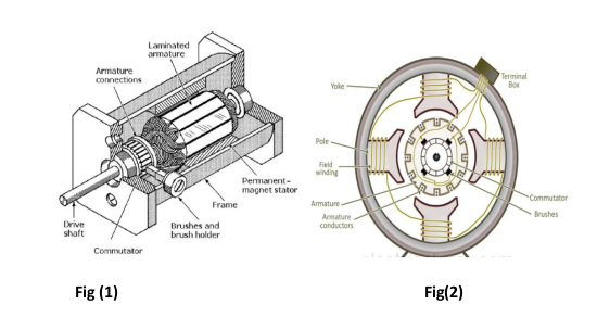
The armature of the DC permanent magnet motor is shown in Figure 2. It is part of the current carrying motor, which interacts with field flux to create torque. The
brush is part of the circuit where the electric current flows to the motor from the power supply — brushes made of graphite or metal. DC motors have one or more
pairs of brushes. One brush is connected to the positive terminal from the power supply, and the other to negative. The commutator is the part that comes into
contact with the brush, which is distributed in armature rolls using brushes and commutators.
2. Speed control
The speed of rotation of motors is directly related to the input voltage. The higher the input voltage, the higher will be the rotational speed of the motor. But the
voltage should be within the operating voltage range.
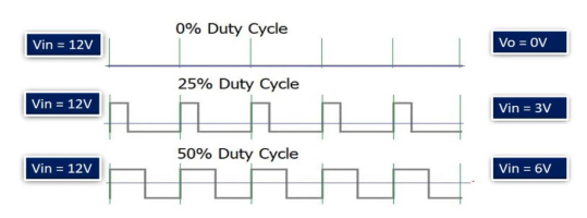
One important point to note here is that if we want to control the speed of a DC motor, we will need to provide a variable voltage to the DC motor. For example, If
the operating voltage range of a motor is between 3 – 6 volts. If we apply 3 volts input, the motor will run at its lowest rated speed. Similarly, if we apply 6 volts, the
DC motor will run at its highest rated speed. In short, we can control the speed of rotation by giving a variable input voltage to a DC motor. Usually, a pulse width
modulation technique is used to generate a variable dc voltage from constant dc voltage source.
2.1 PWM(Pulse Width Modulation)
One method that is often used for DC motor control using a microcontroller is Pulse Width Modulation (PWM) method. The speed of the electric motor depends on the
modulator voltage. The greater the voltage, the faster the rotation of an electric motor. PWM is a good technique for controlling analog circuits of the motor drive
with digital outputs from a microcontroller. PWM is a way to control analog devices with a digital output. PWM is not true analog output, however. PWM “fakes” an
analog-like result by applying power in pulses, or short bursts of regulated voltage.
An example would be to apply full voltage to a motor or lamp for fractions of a second or pulse the voltage to the motor at intervals that made the motor or lamp
do what you wanted it to do. In reality, the voltage is being applied and then removed many times in an interval, but what you experience is an analog-likeresponse.
If you have ever jogged a box fan by applying power intermittently, you will experience a PWM response. The fan and its motor do not stop instantly due to inertia, and so by the time you re-apply power it has only slowed a bit.
Therefore, you do not experience an abrupt stop in power if a motor is driven by PWM. The length of time that a pulse is in a given state (high/low) is the “width” of a pulse wave.
3. Direction Control
We know that in case of DC power supply, there is a concept of polarity such as positive and negative terminals of a battery. The polarity of input voltage source
determines the direction of rotation of a DC motor. For instance, if we connect the positive terminal of battery with one terminal and the negative terminal of battery
with another terminal of DC motor, it will start rotating in clockwise direction. But ifwe interchange the connection of the battery by connecting opposite polarity, the
DC motor will start rotating in another direction as shown in the simulation below.Generally, an H-Bridge circuit is used to provide opposite polarity power to a DC
motor without changing actual power supply connections.
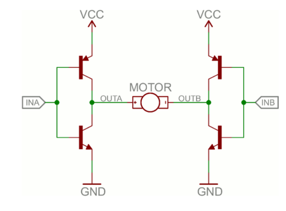
H-bridge
An H-Bridge consists of four switches, resistors, and two control signals as shown in the figure. Two logic probes control the direction of a DC motor. When left probe
logic signal is on, the motor rotates in an anti-clockwise direction and when right probe logic signal is on, the motor rotates in a clockwise direction.
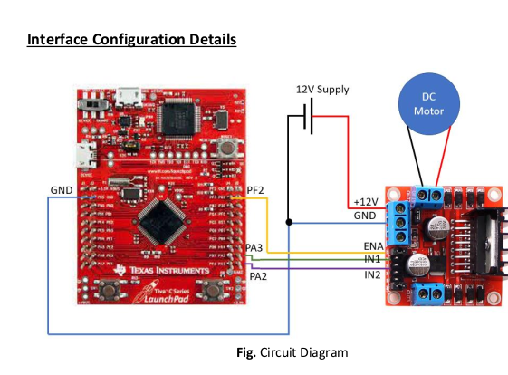
- Pin connections are as follows:
1. GND of TIVA to GND of L298N
2. PF2 of TIVA to ENA of L298N
3. PA3 of TIVA to IN1 of L298N
4. PA2 of TIVA to IN2 of L298N
5. DC motor across OUT1 of L298N
6. 12V DC supply across 12V and GND input of L298N
7.Jumper over ENA removed
8.5V Enable jumper used at COM5
Port Configuration of TIVA C:
1.Enable clock to PWM1 module.
2.Enable system clock to PORTF
3.PF2 sets as alternate function and PWM output selected.
4.Clock enabled to PORT A.
5.PA2 and PA3 set as digital output for controlling the direction of rotation of motor.
Code Organization
The project contains 3 source files and 1 header file.
a. main.c – Calls UART_init() and init_PWM() to initialize UART, UART interrupt and PWM. Then enters infinite while loop.
b. pwm_init.c – Contains the init_PWM() function that initializes the PWM at PF2 and Port PA2 and PA3 for controlling direction of rotation. It loads the PWM to run the
motor at 40% duty cycle at default.
c. UARTIntHandler.c – Contains the function UART_init() to initialize UART and enable UART interrupt. Also, contains the UART interrupt handler routine, which allows the
user to modify the duty cycle through UART input and also change the direction of rotation. Invalid values of duty cycle which gives voltage output outside the
operating ratings of the motor are not accepted. Also, for changing the direction, first output is set to zero then a delay of 3 sec is given to allow the motor to stop
fully before starting the rotation in opposite direction. This prevents burning of motor due to plugging.
Challenges faced:
Since the supply voltage we used was 12V and the motor operating voltage was 4.5 -9V. So care must be taken while taking the duty cycle input so that the modulated voltage does not
exceed the motor rating. Similarly, for braking it is not necessary that 0% duty cycle gives us a zero speed. For example, in our case if we took duty cycle <=10% motor stopped.
Future work:
1. Dead banding: Since H bridge is being used for changing the direction of rotation so there is a possibility of shoot-through current between Source and ground at motor
input. So, bit banding can be used to avoid the situation.
To enable Dead Band, set bit 0 high in PWM1DBCTL and write the amount of delay to be given to the register, PWM1DBRISE.
2. Using Keypad as input for changing the duty cycle and displaying on the LCD display.
demo:
Recent Comments