
Smart Lap Timer :
The aim of this project was to build a device that could record lap counts in a robot car race automatically.
To emulate the interruption we have used an optocoupler limit switch and to display the lap count, we have used PC ( through UART interface ).
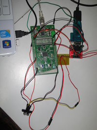
Board Connections
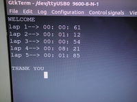
Hyperterminal Display
Function
View
In brief,when ever a participant crosses the finish line an interrupt is generated by the opto sensor to the processor , which takes care of the lap time
record , lap increment and final lap check.
How to Use
After power on , the LCD Display on the STML32 Discovery board reads 0000 S indicating zero seconds have passed and lap timer has not started.
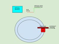
To start the timer the optical path of the sensor should be cut. In order to do this put an obstacle in sensor’s optical path to start the timer.
This action startS the timer and the LCD Display shows the seconds count ( max 3600 seconds).
To complete a lap , user needs to again obstruct the optical path again.This causes
LAP 1 Time to be displayed in PC through UART.
Count (in seconds) reset to 0 in LCD Display. Start Lap 2 count and display the count in LCD Display.
To enter the next lap , the above step needs to be repeated. Our design extends till lap 5, hence once lap 5 is completed, the count is stopped and “thank you” message is displayed indicating finish of laps.
In between any lap, if user button is pressed then
count is cleared to 0 and displayed in LCD . to start laps from 1 again obstruct the sensor path and follow above steps.
After lap 5 if user button is pressed then the count is cleared to 0 and displayed in LCD . to start laps from 1 again obstruct the sensor path and follow above steps.
STM32L Discovery Board
STM32L is an ultralow power discovery board, based on an STM32L152RBT6 microcontroller, featuring 128 KB of Flash memory,16 KB of RAM,4 KB of data EPROM in a 64-pin LQFP package, and includes
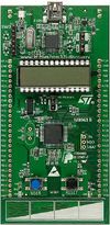
STM32L Board
- an ST-Link/V2 embedded debugging tool interface,
- an LCD (24 segments, 4 commons),
- LEDs,
- pushbuttons,
- a linear touch sensor or touchkeys.
Touch sensor key, GPIOs (USART)and on board 5V and 3.3V supplies on STM32L board are utilised for project.
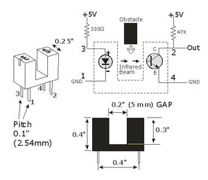
Opto Sensor
STM32L Board
The Sensor we used is called a Slotted Coupler. It is a combination of photo diode and transistor. The photo diode transmits light onto the base of a transistor in idle case. In this case the output is low ( at the collector of the transistor).When the optical path is interrupted , The base turns the transistor off rising the collector voltage to high. To emulate the car crossing the finish line , we interrupt this path between diode and transistor base called slot.
USART interface in synchronous mode
USART features are as follows
- Full duplex, asynchronous communications
- NRZ standard format (Mark/Space)
- Fractional baud rate generator systems.
- Programmable data word length (8 or 9 bits)
- Configurable stop bits – support for 1 or 2 stop bits
- Transmitter clock output for synchronous transmission
- Single wire half duplex communication
- Separate enable bits for Transmitter and Receiver
Note:
There are 3 USART ports available in STM-32L Discovery board. Only USART1 is clocked with PCLK2 (72 MHz Max). Other two USARTs are clocked with PCLK1(36 MHz Max).
Block View
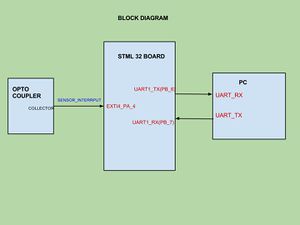
Block Diagram
As shown in the figure, the sensor’s out put is connected to PA_4 which is configured as edge triggered external interrupt EXT4 to the STM32 Board.
After every lap , the recorded time is sent to PC through UART
Transmitter of Board’s UART configured through PB6 is connected to RX of the PC
Receiver of Board’s UART configured through PB7 is connected to TX of the PC
Appraoch
-> ALL the clocks in are system are configured using “RCC_Configuration()” function.
-> All the INTERRUPTs are enabled using “enableInterrupts()” function.
-> Onboard LCD display is initialised to display the time taken by the current lap in seconds using “LCD_GLASS_Init()” function.
-> USART1 is initialised to display the time taken by each lap on the hyperterminal using “my_uart_init()” function.
-> SYSTICK Timer is made ready to be enabled using “project_init()” function.
-> GPIO port (PA.4) is configured as an INTERRUPT SOURCE to sense the sensor using “project_init()” function.
-> Interrupt Service Routine for onboard USERBUTTON is modified to emulate the STOP button using “my_userbutton_handler()” function.
-> Interrupt Service Routine for external interrupt is written to generate control to the STATE MACHINE and display the previous lap time using “my_usersensor_handler()” function. (since, the interrupt occurs on the completion of a lap)
-> State Machine is designed to enable the SYSTICK Timer for each lap and disable it after the stipulated number of laps is over or the user presses the STOP button.
Maing SYSTICK Timer ready to be enabled
-> The COUNTFLAG, CLKSOURCE, TICKINT bits of the SYSTICK Control and Status Register are set.
-> SysTick Reload Value Register is loaded with the count for one second (16000000d)
-> SysTick Current Value Register is cleared to make the timer ready to load the reload value when enabled.
Configuring GPIO port as an interrupt source
->PA.4 is configured as input using GPIO_InitStructure and “GPIO_Init” function.
->PIN 4 is selected as input source for EXTI Line “SYSCFG_EXTILineConfig” function.
->EXTI Line 4 in interrupt mode is configured to be trigged on Rising edge using EXTI_InitStructure and “EXTI_Init” function.
-> EXTI4 Interrupt is enabled and set to the lowest priority using NVIC_InitStructure and “NVIC_Init” function.
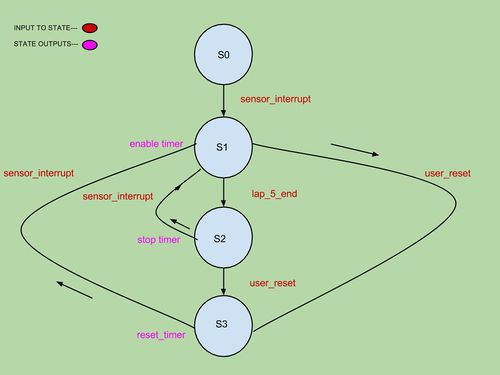
Functioning FSM
Main FSM
Idle state is s0 where all registers initialisation is done and it waits for the trigger( interrupt from sensor output) to start lap count.
As soon as the sensor’s path is cut, it triggers an interrupt which is input to state s0 and the statemachine moves to s1
In State S1 the timer register is enabled. This makes value in the Reload value register to start counting down till zero for one second and again reloads value 0xffffff.Enabling timer register also starts lap 1 . This functionality is included in sensor interrupt ISR.So the seconds display on STM32 LCD keeps incrementing .whenever the optical path of sensor is cut the time taken for lap 1 is recorded and sent on to PC through UART and lap 2’s count starts.
The above process keeps repeating till lap 5
After lap 5 the state machine moves on to state 2 , where lap count stops
When User button is pressed in state 2, state moves to s3 and user interrupt ISR is handled where the timer is reset and count displays 0000 and state machine remains there till a sensor interrupt occurs
When sensor interrupt occurs again state 1 is reached and above processes repeat
In between any lap , if user button is pressed, state changes to s3
Future Work
In the real time robot car race( free scale cup) a laser sensor is used. The opto coupler used in this project could be replaced with the above.
For our project ,for the running lap we are displaying the seconds as a whole on STM32 board’s display whose width restricts display in MM:SS:mm format , this could be implemented on seperate LCD module for better visuals.
As the race demands,a provision to check certain specified distance after final lap could be provided.
References
LECTURE NOTES
Cortex M3 technical reference manual
Project Team Members
Sriram Madavswamy (09337) sriram.madavswamy@gmail.com
Sriram Chintalpudi (09350) sriram.chintalapudi.ese@gmail.com
Recent Comments