
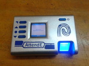
This page describes the Biometric Attendance Register (Attend-E) project, which is a part of the Embedded Systems-1 course. The aim of this project is to build an attendance register that will record attendance by using the finger prints of students. We used PIC18F67K22 micro controller to do this task.
Motivation
Biometric Attendance Register
Professors take reasonable effort in maintaining the record of students attending their classes. They usually call the names of students to mark attendance or pass attendance sheets among students. Their work would have been a lot more easier if they had an electronic attendance register instead. This attendance register can eliminate chances of proxy attendance and can reduce the effort of professors in maintaining the record of students to the click of few buttons.
Developing Idea
Attendance can be recorded by using various methods. But to ensure ease of use and less chances of marking proxy attendance, using finger print seemed to be the best option. Since most people find it easier to work with excel, there should be a method to export attendance details to excel sheet. that of an excel sheet.
Designing Hardware
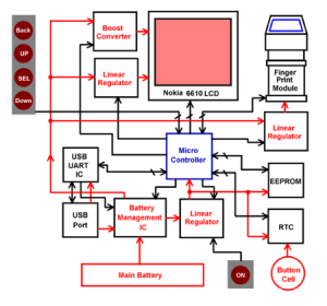
Block Diagram
Sensor
Since using Finger Print Module(FPM) was decided, we chose R305 (register configuration and interface commands similar to R303a) because it is readily available, it has easy to use uart interface and can save upto 255 finger prints.
Microcontroller
The microcontroller should have atleat 2 UARTS(for FPM and PC),2 SPI(Memory and LCD) and 1 I2C(RTC) modules and about 30 GPIO pins. To take care of future enhancements, a 64 pin pic microcontroller, PIC18F67K22 was chosen. This microcontroller has 128KB program memory, 4KB data ram and maximum operating frequency of 64MHz. It has 2 UARTS and an 2 SPI / I2C modules. The 2 SPI modules are used for communicating with Memory and LCD and the I2C module for communicating with RTC is implemented using software.
Real Time Clock
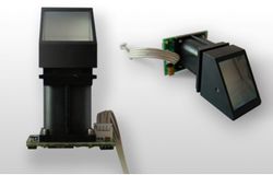
Finger Print Module
The device marks attendance as time stamps. Therefore RTC is required for time keeping. Desirable features include easy to use interface and high accuracy. MCP7940N IC is a good candidate, therefore it is used as RTC. It is a low power IC which works in 3.3V, full binary coded clock/ calendar with I2C interface. This IC provides seconds, minutes, hours, week day, date, month and year with automatic adjustment for months with fewer than 31 days and leap year compensation valid upto 2100. It also has a built-in power-sense circuit that detects power failures and switches to the backup supply.
Memory
Student data involves 31 bytes, in addition to this 6 bytes are required for storing time stamp for each session per student So for 100 students for 100 sessions the memory requirement is
 100 * (31 + 6 * 100) = 63100 bytes

                      = 504,800 bits
In addition to this, some overhead memory is also required for storing validity status of fingerprints, no. of sessions, no. of students etc. The memory should be byte addressable and should consume least no of pins of microcontroller. Flash memory is only sector erasable. So EEPROM is a good solution, Therefore 1Mbit SPI bus EEPROM, 25LC1024 is chosed and interfaced using built in SPI module2. The page size is 256 bytes and operated at 1MHz. The endurance of EEPROM is specified in terms of write cycles / page. So to maximize life time page write(1 write cycle / page) is used instead of byte write (1 write cycle / byte) when ever required. Future implementation may use SD card.
LCD
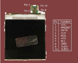
Nokia 6610 LCD
A compact color display with easy to use interface is required. Nokia 6610 LCD satisfies all these requirements. therefore it is used. This LCD has 132rows and 396 columns outputs. 4 Kbyte colours (RGB) = 4:4:4 mode is used. LCD uses Philips PCF8833 controller which communicates with 9 bit SPI protocol. A dedicated 8 bit SPI module of micro controller is used along with bit banging. The first bit which decides whether data is sent or command is send is transmitted by bit banging and the actual data or command is send by the SPI module.
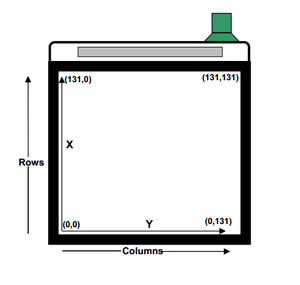
Nokia 6610 LCD Pixel Orientation
Power Management ICs
The device is portable, therefore rechargable Li ion battery is used. Since it needs to be connected to PC, USB port is available. The device is powered via USB and battery is charged when, device is connected to PC, power management ICs take care of this.
Battery Management IC
This IC charges the main LI ion cell. Some of desirable features include Dynamic Power Path Management (DPPM) that charges the battery while simultaneously and independently charging the battery and status indication. Status indication indicates whether the battery is charging/Done, power good. Reverse currrent, short circuit and thermal protection are also required. BQ24073 satisfies all these requirements, therefore it is used. BQ24073 is a 1.5A USB friendly Li-ion battery charger and power path management IC. It can select between 100 mA and 500 mA currents, and has 28V input rating with overvoltage protection.
Linear Regulator
This regulator generates 3.3V dc voltage from 4.2V main cell voltage. The regulator should have minimum dropout voltage. Regulation is better for linear regulator when compared to switching regulator. Also for switching regulator, cost and board space required are more than those required for linear regulator due to presence of inductor, capacitor and diode in switching regulator. Also efficiency increases with load current for switching regulator while efficiency decreases with load current for linear regulator. Since we are using low load current, linear regulator is more efficient. therefore, a linear regulator IC, TPS73633 is chosen. This regulator has 1 % regulation over line, load and temperature. It has ultra low drop out voltage of 75mV. and input voltage range of 1.5 to 5.5V. It also has an enable pin that enables the software to selectively turnoff of the IC.
Three linear regulators are used.
1. For powering Finger Print Module.
2. For powering LCD
3. For powering other ICs.
Boost Converter
Boost converter is required in LCD board to obtain 7V dc to drive LCD backlight from 4.2 V supply voltage. This enables the backlight and the LCD to be turned off separately. This converter should have an enable pin, should preferably use current mode control and have high feed back accuracy. LM2735 satisfies all these requirements. It has ultra low standby current of 80nA in shutdown, 2% feedback voltage accuracy and input voltage range from 2.7V to 5.5V. Output voltage can be fixed between 3V to 24V. Here output voltage is fiixed at 7V. In addition to L2735 has internal compensation and internal soft start features.
Battery
Current consumption by various components are listed below.
Power budget
| Component | Active mode | Inactive/Sleep mode | |
| 1. | FPM module | 150mA | – |
| 2. | Micro controller | 19mA | 2.7uA |
| 3. | EEPROM | 5mA | 12uA |
| 4. | RTC | 1.5mA | 200uA |
| 5. | LCD | 20mA | 1100uA |
| 6. | Power management ICs | 1.5mA+1uA+10uA | 50uA+80nA+1uA |
Total Active current  = 150mA + 19mA + 5mA + 1.5mA + 20mA + 1.5mA = 197mA
Total Standby current = 2.7uA + 12uA + 200uA + 1100uA + 51uA = 1.366mA
Battery Backup Time
Assuming 40% time as active time.
Average current = 197mA * 0.4 + 1.366mA * 0.6 = 79.6mA
Assuming device is operated for 2 hours daily and expected battery backup duration is 10 days,
mAH rating of main battery = 79.6 * 2 * 10 = 1592 mAH
Operating voltage of FPM, microcontroller, RTC and memory = 3.3V
Taking these two requirements into consideration, 4.2V 2000mAH Li ion battery is used as main battery.
				  2000mAH
Standby Time		   =    -----------   =   1464 hours = 61 days
				  1.366mA

				  2000mAH
Average Working Time       =    -----------   =   25 hours
			          79.6mA
RTC requires backup supply to maintain time even if main battery completely discharges or it is removed. Therefore 3V button cell is used as backup supply. As long as atleast one battery is present, RTC maintains time.
Adding on Intelligence to Hardware
Memory Map
The page size is 256 bytes.
				    1024 * 1024
No. of pages available	   =	    -----------   =   512 pages
				      8 * 256
Of these the first page is used for saving validity of finger prints. Byte 0x0 saves validity of admin and bytes 0x1 to 0x64 saves validity of 99 students. The fist 2 bytes of seconnd page 0x100 and 0x101 (col = [0x100][0x101]) stores offset address of previous session. Each student is assigned a number(index no.) from 1 to 100 depending on the position of fingerprint in memory of FPM. Admin is always assigned index no. 0.
Page 3 to page 5 are used for storing session date(ddmmyy) information. From page 6, each student is allotted 3 pages. The first 31 bytes stores student index no.(1 byte), name(15 bytes), srn/admission no. (10 bytes) and department details(5 bytes). Remaining 737 byte (256 * 3 – 31) are used for storing attendance status for each student. 0x FFFF FFFF FFFF indicates student is absent for that session, While any other value indicates student is present and the value indicates time stamp (hh:mm ).
To ensure long life of device, page write is used instead of byte write. But page write can be used only for bytes in same page. Therefore, no session time stamp should overlap in two pages, this correction is done.
256 - 31    256     256
Max No. of sessions available    =  --------- + ----- + ------    =   121
				       6	  6       6

                                     512 - 2
Max No. of students possible     =  ---------   =  170
				        3
Algorithm
Main Program
A state machine is used to allow the software to update the time and battery status continuously.
0.  START
1.  Initialize oscillator, pins, latch power, uart, eeprom, rtc time string, fpm, interrupts, LCD and sleep flag.
2.  Read meta data.
3.  Read RTC time and battery level.
4.  Display welcome screen.
5.  Enter into state machine
6.  If sleep flag = 0 goto 9
7.  sleep with wake up
8.  when interrupted, Read RTC time and battery level and display them on screen.
9.  If RTC_flag = 0 goto 12
10. Clear RTC flag
11. Read RTC time and battery level and display them on screen.
12. If admin = set goto 16
13  Set admin
14  If admin_set = success goto 16
15  Poweroff
16. Display Home screen enable button interrupts

17. If option != 0 goto 31
18. If Button_press = Back goto 16
19. If Authentication = fail goto 18
20. Read previous session header
21. Display Session Screen
22. Disable button interrupts.
23. Scan fingerprint.
24. If fpm_id != admin goto 27
25. Show confirm window
26. If confirm = Yes goto 16
27. If fpm_id != any student goto 23
28. Read RTC time
29. Save Time stamp
30. Goto 23

31. If option != 1 goto 37
32. If Button_press = Back goto 16
33. If Authentication = fail goto 32
34. Read previous session header
35. Increment previous session header
36. Goto 21

37. If option != 2 goto 58
38. If Button_press = Back goto 6
39. If Authentication = fail goto 38
40. Display synchronize menu
41. If option7 != 0 goto 44
42. Display Uploading screen
43. Send data to PC
44. If Sync = success goto 47
45. Display Sync fail screen
46. Goto 38
47. Display Sync success screen
48. Goto 38
49. If option7 != 1 goto 53
50. Display Downloading screen
51. Receive data from PC
52. Goto 44
53. If option7 ! = 2 goto 38
54. Display Time sync screen
55. Receive time data from PC
56. Change device time.
57. Goto 44

58. If option != 3 goto 73
59. If Button_press = Back goto 6
60. If Authentication = fail goto 59
61. Display Add student screen
62. Disable button interrupts.
63. Scan fingerprint.
64. If fpm_id != admin goto 67
65. Show confirm window
66. If confirm = Yes goto 16
67. If fpm_id != any student goto 70
68. Display Duplicate Finger Print Screen
69. Goto 63
70. Save Student
71. Show Success Window and student ID
72. Goto 63

73. If option != 4 goto 90
74. If Button_press = Back goto 6
75. If option4 != 0 goto 82
76. Show Reset confirm window
77. If confirm = No goto 74
78. Show Authentication Window
79. If Authentication = fail goto 74
80. Delete Admin
81. Switch off device.
82. If option4 != 1 goto 74
83. Show Reset confirm window
84. If confirm = No goto 74
85. Show Authentication Window
86. If Authentication = fail goto 74
87. Erase FPM
88. Erase EEPROM
89. Switch off device.

90. If option != 5 goto 6
76. Show Turn off confirm window
91. If Button_press = Back goto 6
92. If confirm = No goto 6
93. Show Good Bye Screen
93. Switch off device

94. END
Interrupt Service Routine
0.  START
1.  If interrupt != RTC_interrupt goto 12
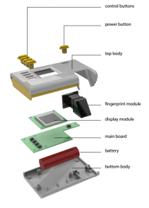
Exploded diagram
2.  Disable RTC_interrupt
3.  Clear RTC_interrupt

4.  Increment RTC_count
5.  If RTC_count != 120 goto 8
6.  RTC_flag = 1
7.  RTC_count = 0

8.  Increment sleep_count
9.  If sleep_count != 25 goto 12
10. sleep_flag = 1
11. sleep_count = 0
12. Enable RTC_interrupt

13. If Back_button != Pressed goto 19
14. Debounce back button
15. Clear Button interrupt.
16. Button_press = Back
17. sleep_flag = 0
18. sleep_count = 0

13. If Back_button != Pressed goto 19
14. Debounce BACK button
15. Clear Button interrupt.
16. Button_press = BACK
17. sleep_flag = 0
18. sleep_count = 0

19. If UP_button != Pressed goto 25
20. Debounce UP button
21. Clear Button interrupt.
22. Button_press = UP
23. sleep_flag = 0
24. sleep_count = 0

25. If SELECT_button != Pressed goto 31
26. Debounce SELECT button
27. Clear Button interrupt.
28. Button_press = SELECT
29. sleep_flag = 0
30. sleep_count = 0

31. If Back_button != Pressed goto 37
32. Debounce DOWN button
33. Clear Button interrupt.
34. Button_press = DOWN
35. sleep_flag = 0
36. sleep_count = 0

37. END
Source code
Source code can be found in moodle.
Synchronizing with excel
The attendance registered in the device can be uploaded into excel sheet. This is done by installing an ActiveX Control (Stroke Reader). Excel Visual
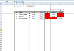
Excel Sheet
Basic Application is running as the background process in excel sheet. All synchronizing operations are initiated by Attend-E. There are three types of synchronizing operations.
1. Uploading attendance from Attend-E to PC.
2. Downloading student details from PC to Attend-E.
3. Synchronizing time in Attend-E with PC time.
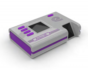
Packaging
The device should be as compact as possible and have ergonomic and aesthetic design. The body is designed by Jince M.P in CPDM, IISc and PCB is custom made in Proteus as per the body design. The Rapid Prototyping machine ( 3D printer ) in CPDM, IISc is used to make the device body and metallic spray paint is used to enhance its aesthetics.
Procedure for Operating Attend-E
1. Initially the device will be in factory reset mode.
2. Assign Admin.
3. Add students.
4. Type student details in Excel sheet.
5. Download student details into Attend-E  from PC.
6. Synchronize device time with PC time.
7. Start a New Session and start taking attendances.
8. Upload student attendance from Attend-E to PC.
9. Repeat 6,7 and 8 when required.
Snap Shots
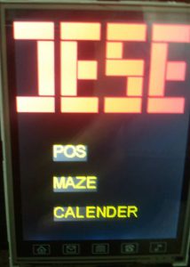
Attend-E
Main Menu
Authentication Menu
Project Team
- Anish G S (mail.anishgs@gmail.com)
- Mathews Boby (mathewsboby00@yahoo.com)
Recent Comments