
About the project
This project was done as part of course work for Embedded Systems Design-I, taught by Prof. Haresh Dagale and Prof. Sudhakar. Project was done by:
- Aakriti Gupta (SERC, M.Tech.)
- Mohit Dhingra (SERC, M.Sc.)
Introduction
A bootloader is a program that runs at processor reset and may accept a new firmware image which is used to reprogram the device’s flash. If the bootloader times out while waiting for a new image it exits and launches the code previously stored in the flash.
Bootloader Requirements
- Resides in its own region of flash which is never erased by the bootloader
- Runs immediately following reset
- If receives a signal within a certain amount of time, bootloader downloads an image and then reprograms the application area of the flash with the received image.
- If does not receive the any signal within a certain time period, bootloader transfers execution to the stored application
The aim of this project was to create two banks in flash memory for storing user application code or main function. It is desired that at least one of the banks will always store consistent and correct image that can be loaded and run. While the code is running from one bank, the functionality to program the second memory bank should be provided. On soft reset, the bootloader code shall run and wait for a new image and load it into the other memory bank and jump to the start of this freshly written code. (Future work here could be to include checksums etc and check the correctness of this code before executing it).
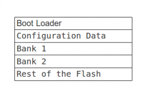
Theory and logistics
Logically, flash is divided as follows. The size of each partition can vary depending on the requirements.
Implementation
- GPIO and USART configurations were done inside the boot loader C code.
- External LED is connected to a fixed GPIO in out mode. As soon as restart occurs, this LED is turned on to indicate that system is waiting for some booting signal.
- User can press ENTER in the USART terminal to go into booting mode while the LED is on.
- If user doesn’t do that, after about 2 seconds of wait, the pre-stored user application function is called.
- Currently, in boot mode, image is being copied from one BANK to another. In future getting a relocatable image from USART is to be implemented.
Changing linker command file
We need to change the linker command file in the following ways:
- Changing the memory partition. This includes creating a separate section for bootloader, creating memory banks for storing application code. The region for bootloader is read only, even for bootloader itself. Whereas, the region for memory banks may be reprogrammed by bootloader. Both reside in FLASH.
 MEMORY
 {
  FLASH (rx)      : ORIGIN = 0x08000000, LENGTH = 120K
  BANKONE (rx)    : ORIGIN = 0x0801f000, LENGTH = 1K
  BANKTWO (rx)    : ORIGIN = 0x0801f600, LENGTH = 1K

  etc.
 }
- Creating new sections for bootloader and application function (main).
 /* Application code goes into FLASH */
 .my_main :
 {
   . = ALIGN(4);
   KEEP(*(.my_main))
   . = ALIGN(4);
 } >BANKONE
- Optionally, we can change the entry point into the main if we wish to execute some code before executing the reset handler.
 /* Entry Point */
 ENTRY(My_Boot)
File location: STM32L_Discovery/LinkerScript/stm32_flash.ld
Changing startup code
We need to change the startup file in the following ways:
- A small bootloader code is written. It resides in boot section.
- Reset Handler is made to call another function, which contains the bootloader implementation in C, before it calls main.
- Changing the isr vector to call bootloader instead of Reset Handler. Reset Handler is called from within bootloader code.
 .section .bootloader.My_Boot
   .weak My_Boot
   .type My_Boot, %function
 My_Boot:
   bl my_func
   b Reset_Handler
   .size My_Boot, .-My_Boot
File location: STM32L_Discovery/Startup/startup_stm32l1xx_md.S
BootLoader Code
- To send a particular C function to a particular section in memory, following statement is written before the start of that function.
__attribute__((section(".bootloader")))
Programming Flash
Any operation of erase or program should follow these steps:
- Call the FLASH_Unlock() function to enable the flash control register and program memory access
- Call the desired function to erase page or program data
- Call the FLASH_Lock() to disable the flash program memory access (recommended to protect the FLASH memory against possible unwanted operation)
Flash erase
Function FLASH_ErasePage(uint32_t Address) is used to erase any given page(1K bytes) in flash memory. Potentially, we can erase any page in the Program memory if the address to load is the start address of a page (multiple of 256 bytes). This is because flash can only be erased page-wise unlike flash write, which can be done byte/word wise.
 FLASH_Unlock();
 FLASH_ClearFlag(FLASH_FLAG_EOP);
 FLASH_ErasePage(PAGE_ADDRESS);
 FLASH_Lock();
In this case we have to protect the bootloader code from being overwritten.
Add: How this protection is being done.
Flash write
Function FLASH_FastProgramWord(uint32_t Address,uint32_t Data) is used to program the flash memory word by word. Sample code to do memcopy from one flash bank to another:
 _DPAGE = 0x0801f600; //Destination Address (BANK 2)
 _SPAGE = 0x0801f000; //Source Address (BANK 1)
 for(i=0;i<size;i++)
 {
   VAL = *(uint32_t *)(_SPAGE+i*4);
   FLASH_FastProgramWord(_DPAGE+i*4,VAL);
 }
File location for reference: STM32L_Discovery/STM32L1xx_StdPeriph_Driver/src/stm32l1xx_flash.c
Future Work
- Download relocatable image from USART.
- Include checksums etc to check the correctness of the newly downloaded code before executing it.
- Creating a user interface to get booting options.
References
- AN2606 Application note – My ST Login – STMicroelectronics
- Data Sheet CD00240193 for: Microcontrollers (MCU)
- AN3155 Application note USART protocol used in the STM32TM bootloader
Recent Comments