
Introduction: The aim of the project is to collect audio data, separate the frequency components of the data into eight bands spanning 20 Hz to 20 KHz and display them as a bar graph. This project is a part of the embedded system design-I course at DESE, IISc.
Hardware Platform
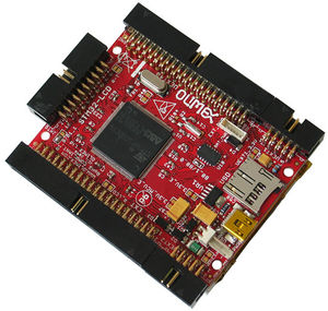
We used the “STM32-LCD” development board from Olimex. The board has the following features:
MCU– STM32F103ZE:
- high-performance ARM® Cortex™-M3 32-bit RISC core operating at a 72 MHz frequency,
- Flash memory – 512 Kbytes
- SRAM – 64 Kbytes
- Extensive range of enhanced I/Os and peripherals connected to two APB buses.
- JTAG connector
- LCD TFT 320×240 pixels 12 bit colour with touch screen.
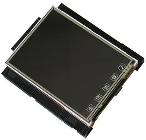
Front view
-
Back view
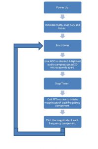
The Program flow can be divided into three sequential steps
- 1. Data acquisition
- 2. Signal processing
- 3. Display Results
Data Acquisition
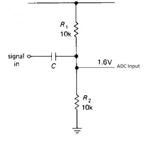
In this stage the audio signal input is digitized. The ADC on the stm32f103ze processor is a 12 bit successive approximation type. The ADC reference voltage pin is connected to the supply voltage (3.3V) of the microcontroller. Since the audio signal has voltage levels both positive and negative with respect to ground, we need to suitably level shift the input signal. This is done by the interfacing circuitry shown below.
-
Since we are interested in signals up to 20 KHz, we must sample at least at 40 KHz (Nyquist rate).
We choose 50 KHz (2.5 times) as our sampling frequency. The ADC is triggered using timer 1 in output compare mode.
For eight frequency bands we need to calculate 16 point dft. The timer is activated to start sampling audio data.
 After ADC has converted 16 values the timer is switched off.
-
Signal processing
The spectrum of the audio signal is obtained using the discrete Fourier transform. Fast Fourier transform is a class of algorithms that efficiently compute the DFT. FFT requires O((N/2)log(N)) complex multiplications as opposed to O(N¬2) required for direct DFT computation. In case of real valued inputs, as in our case, the number of complex multiplications required can be further reduced by half.
The block diagram shown below depicts decimation in time FFT.
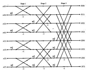
Before performing the FFT the input sequence is multiplied by Hanning window to reduce spectral leakage.
The stm32f103ze processor doesn’t have hardware support for floating point operations. Hence we decided to use fixed point math; specifically we adopted the libfixmath library which uses Q16.16 format. http://code.google.com/p/libfixmath/wiki/Benchmarks shows performance benchmarks of q16.16 over emulated floating point on a cortex m3.
-
Display Results
The magnitude of each frequency bin is displayed as a bar with 10 levels. Increase in each level corresponds to 3dB increase in power. To test the application the audio output port of a cell phone was interfaced to the microcontroller. The results are shown below.
-
Reference
- 1. http://www.olimex.com/dev/index.html
- 2. Understanding Digital Signal Processing: Richard G Lyons
- 3. http://www.cmlab.csie.ntu.edu.tw/cml/dsp/training/coding/transform/fft.html
- 4. http://code.google.com/p/libfixmath/
Recent Comments