
The miniproject is titled DIGITAL PHOTO FRAME . The aim is to build a digital photo frame with a touch sensor. It scrolls images when slide keys are touched , having the effect of sliding of the images. It is implemented using STM32L Discovery Board with an add on board to house Nokia 6610 Graphics LCD. Nokia 6610 LCD is 132 x 132 pixel 12 bit colour TFT LCD with backlight.
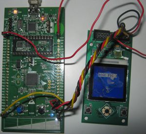
Digital Photo Frame
STM32L Discovery Board
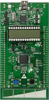
STM32L Board
STM32L is an ultralow power discovery board, based on an STM32L152RBT6 microcontroller, featuring 128 KB of Flash memory,16 KB of RAM,4 KB of data EPROM in a 64-pin LQFP package, and includes
- an ST-Link/V2 embedded debugging tool interface,
- an LCD (24 segments, 4 commons),
- LEDs,
- pushbuttons,
- a linear touch sensor or touchkeys.
Touch sensor key, GPIOs (USART)and on board 5V and 3.3V supplies on STM32L board are utilised for project.
Nokia 6610 LCD Add-On board
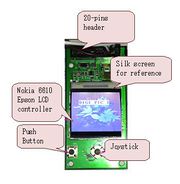
LCD Add-On Board
The add-on board has
- Provision to connect Nokia 6610 LCD,
- Provision for MicroSD-Card,
- Two Push buttons,
- Joystick.
The board has a 20-pin header available through which LCD and other features could be connected. Nokia 6610 Graphics LCD with S1D15G00 epson controller is utilised for this project.
LCD Add-On Board
Nokia 6610 LCD
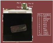
Nokia 6610 LCD
Nokia 6610 LCD
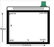
The Nokia 6100 display has 132 x 132 pixels; each one with 12-bit color (4 bits RED, 4 bits GREEN and 4 bits BLUE). The orientation is as shown in figure. The S1D15G00 epson controller has a 17424 word memory (132 x 132), where each word is 12 bits
Notes:
1. Once the drawing boundaries have been fixed, any subsequent memory operations are confined to that boundary. Pixels defined beyond the boundaries are discarded by the controller.
2.Practically , the first and last row and columns cannot be seen.
S1D15G00 Epson controller
Nokia 6610 LCD
The Epson LCD controller has three different ways to specify a pixel’s color.
1. 12 bits per pixel
2. 8 bits per pixel Selection of the reduced resolution
3. 16 bits per pixel
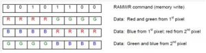
The wrap-around feature is the cornerstone of the controller’s design . This feature allows to efficiently draw a character or fill a box with just a simple loop -after writing the pixel in the last column and auto-incrementing to the next row.
SPI interface
NOKIA 6610 LCD has two-wire serial SPI interface (clock and data) and the display acts solely as a slave device. Therefore, the display is strictly write-only. 9 bits are to the display serially, the ninth bit indicates if a command byte or a data byte is being transmitted.
Interfacing of Nokia LCD to STM32 L Discovery
Epson LCD controller requires a serial data transmission of 9 bits size. But, SPI peripheral on STM32L supports either 8-bits or 16-bits datasize. To interface them there are broadly two ways,
the data transfer done through USART in synchronous mode
( or )
emulate SPI for 9-bits of serial data transmission by bit-banging
USART interface in synchronous mode
USART features are as follows
- Full duplex, asynchronous communications
- NRZ standard format (Mark/Space)
- Fractional baud rate generator systems.
- Programmable data word length (8 or 9 bits)
- Configurable stop bits – support for 1 or 2 stop bits
- Transmitter clock output for synchronous transmission
- Single wire half duplex communication
- Separate enable bits for Transmitter and Receiver
Note:
There are 3 USART ports available in STM-32L Discovery board. Only USART1 is clocked with PCLK2 (72 MHz Max). Other two USARTs are clocked with PCLK1(36 MHz Max).
USART1 is enabled with following specifications
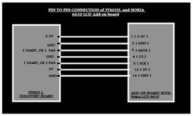
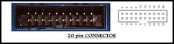
USART Interface Pin connection
- Enable peripheral clock for USART1 using function RCC_APB2PeriphClockCmd.
- According to the USART mode, enable the GPIO clocks using RCC_AHBPeriphClockCmd.
- Peripheral’s alternate function:connect the pin to the desired peripherals’ Alternate Function (AF) using GPIO_PinAFConfig() function
- Select the type, pull-up/pull-down and output speed via GPIO_PuPd, GPIO_OType and GPIO_Speed members
- Call Init_GPIOs() function
- Program the Baud Rate, Word Length , Stop Bit, Parity, Hardware flow control and Mode(Receiver/Transmitter) using the USART_Init()function.
- For synchronous mode, enable the clock and program the polarity,phase and last bit using the USART_ClockInit() function.
- Enable the USART using the USART_Cmd() function.
Note:
Baudrate of USART in synchronous mode can be changed for varied data transfer speed.
Bit Bang Method of SPI Emulation
Bit Banging Pin Connection
GPIO Pins PB15 and PB13 are used for clock and data (MOSI) purpose respectively.
Note: However 4 wire serial communication can be done using A0 pin apart from sck, mosi, cs’ available with 3 wire serial communication. This enables 8 bit SPI peripheral available with STM32L
Advantage of using USART over bit bang method
- A better serial clock signal with uniform clock period is observed since a dedicated peripheral is used.
- Ease of serial communication with USART instead of writing tedious code of toggling GPIOs for data(MISO) and clock(SCK) signals.
Touch Slide
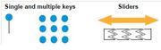
Touch Slide
STMTouch firmware library provides surface capacitive touchsensing capabilities STM32L MCUs.
It has following features
- Easy integration of keys and sliders to replace conventional electromechanical switches in human interfaces.
- Solution for acquisition, post processing and API layers, debounce filtering, calibration functions, environment change system (ECS).
- Multi-function capability to combine capacitive sensing functions with traditional MCU features (including communication, LED control, beeper, LCD control).
Algorithm for touch sensor key
      Step 1: Initialise touch slide keys
      Step 2: Run Touch slide function (includes acquisition and processing of keys with debounce filtering)
      Step 3: Decide slider value and perform required action
              (includes a counter that counts as long as slide is touched,
               Performs required action i.e., sliding images,
               LED indication is enabled i.e., toggling )
      Step 4: Steps 2 and 3 are run in infinite while loop
Note: The above implementation can also be an interrupt based code
Slide Effect of Images
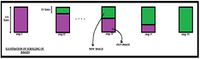
Scrolling of Images
This is achieved by suitably writing display with new image and old image in sections. With suitable clock frequency it gives the effect of sliding image. This is depicted in the figure
Algorithm for image slide
       Step 1: Decide on the number of lines to be written, say 25 lines
               Size of each line = 132(pixels) x 12 bit / 8 = 198 B
               Size of 25 lines = 4950B
               A group of 25 lines is denoted as a chunk
       Step 2: Each time number of chunks to be displayed from new image is increased by one chunk and that of old image
               is decreased by 1
       Step 3: Iterate the above steps for 132/25 = 6 times
Note: The image is to be reversed and displayed for sliding effect . Else manipulate the index of the image buffer (i.e., constant hex array)
Flow of implementation
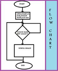
Flow Chart
Algorithm
    Step1: Initialise GPIOs with Init_GPIOs(). Provide clock configuration using RCC_Configuration()
    Step2: Initialize LCD with InitLcd() (user defined) and touch sense key using TSL_Init()
    Step3: Check if sense keys are touched.
    Step4: If 'yes' start sliding the image, else proceed to step (5)
    Step5: Go to step (3)
Note:
1. InitLCD() is a user defined function to initialise LCD. Its implementation depends on the type of LCD controller available.
2.Size of image is restricted to 131 x 131 pixels.
3. Convert ‘bmp’ images to hexadecimal array using bmp to hex converter. Refer to following site [1]
4.Due to the limit on the amout of ‘rodata’ i.e., constants not many images can be stored within code for display.
Clock and Data Waveforms for USART
Data of 9 bits and corresponding 9 clock cycles can be observed in figure

Clock and Data Waveform
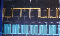
Clock and Data Waveform in detail
Future Work
- Picture zoom can be implemented.
- Interrupt based code can be done.
- Improvised ways to store many images of big size.
References
1.STM32L Discovery details available on below site
STM32L-DISCOVERY
2.STM32L reference manual File:Rm008.pdf
3.Nokia LCD 6610 Tutorial File:Nokia_6100_LCD_Display_Driver.pdf
4.S1D15G00 Epson controller for Nokia 6610 LCD File:S1D15G00_REV1_0_NOKIA6610.pdf
5. STM32L Discovery schematic File:Stm32l.pdf
Project Team Members
- Neela Pavani T
- P.Chandhini
Recent Comments