
In the previous article, we showed how to program the timers. In those programming examples, we used polling to see if a timeout event occurred. In this section, we give interrupt-based version of those programs. Examine the earlier programs, we could run those programs only one at a time since we have to monitor the timer flag continuously. By using interrupt, we can run several of timer programs all at the same. To do that, we need to enable the timer interrupts using the GPTMIMR (GPTM Interrupt Mask) register.
Timers A and B Interrupt and Configuration Register Group
Six registers are used to control and handle interrupts of the Timers A and B:
- GPTM Interrupt Mask Register (GPTMIMR)
- GPTM Raw Interrupt Status Register (GPTMRIS)
- GPTM Masked Interrupt Status Register (GPTMMIS)
- GPTM Interrupt Clear Register (GPTMICR)
- GPTM Synchronize Register (GPTMSYNC)
- GPTM Peripheral Properties Register (GPTMPP)
GPTM Interrupt Mask Register (GPTMIMR)
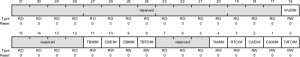
| Bit | Name | Description |
|---|---|---|
| 0 | TATOIM | Timer A Time-out Interrupt Mask (0: interrupt is disabled, 1: interrupt is enabled) |
| 1 | CAMIM | Timer A Capture Mode Match Interrupt Mask (0: interrupt is disabled, 1: interrupt is enabled) |
| 2 | CAEIM | Timer A Capture Mode Event Interrupt Mask (0: interrupt is disabled, 1: interrupt is enabled) |
| 3 | RTCIM | RTC Interrupt Mask (0: interrupt is disabled, 1: interrupt is enabled) |
| 4 | TAMIM | Timer A Match Interrupt Mask (0: interrupt is disabled, 1: interrupt is enabled) |
| 8 | TBTOIM | Timer B Time-out Interrupt Mask (0: interrupt is disabled, 1: interrupt is enabled) |
| 9 | CBMIM | Timer B Capture Mode Match Interrupt Mask (0: interrupt is disabled, 1: interrupt is enabled) |
| 10 | CBEIM | Timer B Capture Mode Event Interrupt Mask (0: interrupt is disabled, 1: interrupt is enabled) |
| 11 | TBMIM | Timer B Match Interrupt Mask (0: interrupt is disabled, 1: interrupt is enabled) |
| 16 | WUEIM | 32/64-Bit Wide GPTM Write Update Error Interrupt Mask (0: disabled, 1: enabled) |
IRQ21 is assigned to Timer1A and IRQ23 to Timer2A. The following will enable these timers in NVIC:
NVIC_EN0_R |= 0x00200000;   /* enable IRQ21  */
NVIC_EN0_R |= 0x00800000;   /* enable IRQ23 */
GPTM Raw Interrupt Status Register (GPTMRIS)
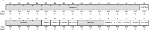
This 32-bit register only used the lower 10 bits to monitor and set a raw or internal interrupt if a GPTM-related raw interrupt occurred. These bits are set whether or not the interrupt is masked in the GPTMIMR register. However, whether these set raw interrupts can be sent to the interrupt controller to be further processed, it depends on whether the corresponding bits on the GPTMIMR register are set (enabled) or not (disabled). Only for those bits that have been set on the GPTMIMR register, they can be sent to the NVIC. The bit field and functions for this register are similar to those in the GPTMIMR register. If a GPTM-related raw interrupt is generated, the corresponding bit on this register is set to 1. Each bit can be cleared by writing a 1 to its corresponding bit in GPTMICR register.
| Bit | Name | Description |
|---|---|---|
| 0 | TATORIS | Timer A Time-out Raw interrupt (0: not occurred, 1: occurred) |
| 1 | CAMRIS | Timer A Capture Mode Match Raw Interrupt (0: not occurred, 1: occurred) |
| 2 | CAERIS | Timer A Capture Mode Event Raw Interrupt (0: not occurred, 1: occurred) |
| 3 | RTCRIS | RTC Raw Interrupt(0: not occurred, 1: occurred) |
| 4 | TAMRIS | Timer A Match Raw Interrupt |
| 8 | TBTORIS | Timer B Time-out Raw interrupt (0: not occurred, 1: occurred) |
| 9 | CBMRIS | Timer B Capture Mode Match Raw Interrupt (0: not occurred, 1: occurred) |
| 10 | CBERIS | Timer B Capture Mode Event Raw Interrupt (0: not occurred, 1: occurred) |
| 11 | TBMRIS | Timer B Match Raw Interrupt |
| 16 | WUERIS | 32/64-Bit Wide GPTM Write Update Error Raw Interrupt Status |
GPTM Masked Interrupt Status Register (GPTMMIS)
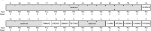
Similar to the GPTMIMR register, this 32-bit register only used the lower 10 bits to monitor and make a responded interrupt if a GPTM related interrupt is occurred and has been responded. The bit field and functions for this register is similar to those in the GPTMIMR register. A value of 1 on a bit in this register indicates that the corresponding interrupt has occurred and has received a response. All bits are cleared by writing a 1 to the corresponding bit in GPTMICR register.
GPTM Interrupt Clear Register (GPTMICR)
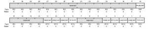
Similar to GPTMIMR register, this 32-bit register only used the lower 10 bits to clear related responded interrupts if the GPTM-related interrupts have received a response and have been processed. This register is used to clear the status bits in the GPTMRIS and GPTMMIS registers. Writing a 1 to a bit clears the corresponding bit in the GPTMRIS and GPTMMIS registers. All processed or responded interrupts must be cleared by using this register. Otherwise the responded interrupt cannot be generated again in the future if it is not cleared. The bit field and functions for this register is similar to those in the GPTMIMR register.
Recent Comments