
I.INTRODUCTION
1.1 overview of edge AI
Edge AI represents a paradigm shift where machine learning workflows are executed on local embedded devices rather than centralized cloud servers. By processing data directly at the source, this architecture eliminates the latency and bandwidth costs associated with transmitting raw video streams to the cloud. Edge AI is critical for real-time systems, ensuring immediate response times, enhanced data privacy, and operational capability even in the absence of internet connectivity.
We propose the implementation of a 3-node GPU cluster using NVIDIA Jetson Nano developer kits, orchestrated by K3s (Lightweight Kubernetes).
1.2 Hardware Requirements
To achieve the proposed architecture, the following hardware components were used:
- Compute Nodes: 3x NVIDIA Jetson Nano Developer Kits (4GB Model) equipped with 64GB Class 10 MicroSD cards.
- Networking: 1x 8-Port Gigabit Ethernet Switch and 3x CAT6 Ethernet cables (connecting nodes and uplink).
- Power and Cooling: 3x 5V/4A DC Barrel Jack power supplies
II.SYSTEM CONFIGURATION AND NODE SETUP
This section details the preparation of the hardware and operating system required to create a distributed edge cluster. The following steps were applied identically to the master node and the three worker nodes to ensure a uniform environment.
2.1 Initial Preparation and Flashing
The cluster utilizes the NVIDIA Jetson Nano Developer Kit. The initial setup involved flashing the operating system onto microSD cards.
- The official Jetson Nano Developer Kit SD Card Image was downloaded from the NVIDIA developer website.
- The image was flashed onto high-performance microSD cards using
- The cards were inserted into the Jetson Nano
- A monitor, keyboard, mouse, and 5V/4A DC power supply were connected to each unit to facilitate the first boot process.
2.2 First Boot and Hostname Assignment
Upon the first boot, the Ubuntu-based JetPack OS configuration wizard was completed (selecting language, keyboard layout, and creating a user account). To identify nodes within the cluster network, unique hostnames were assigned to each device during the installation process. The hostnames can also be changed later(post-setup) using the command on each node:
sudo hostnamectl set−hostname desired hostname We used the following hostnames:
- user-desktop(Master)
- user-worker(Worker 1)
- user-newworker(Worker 2)
To avoid issues later on, each hostname should be different(more on that in 8)
2.3 Network Infrastructure and IP Configuration
Due to strict security protocols on the ”iiscwlan” (which blocks custom DNS and static IP assignment), an isolated local network was established to ensure consistent communication between the cluster nodes.
2.3.1 Gateway Setup
A laptop running Ubuntu 22.04 was configured to act as the network gateway. The laptop was connected to an unmanaged network switch. Each jetson was also connected to this switch after configuring static IPs. This setup allowed the cluster to remain on a private subnet while accessing the internet for package updates and image pulling.
- Upstream Connection: The laptop was connected to a mobile hotspot to provide internet access, bypassing ”iiscwlan” restrictions.
- Downstream Connection: The laptop’s Ethernet interface was connected to the cluster’s network switch.
- Interface Configuration: The ”Shared to other computers” method was selected in the Ubuntu Network Settings (IPv4). By default, Ubuntu assigns IP addresses in such configuration in the subnet 10.42.0.1/24. This causes an issue described in
- The IP address of this gateway interface was manually set to cover a wide subnet range:
- IP Address: 168.0.1
- Subnet Mask: 255.0.0 (/16)
This was done using the following commands on the laptop: nmcli connection down ” Wire le s s – connection – 1 ”
nmcli connection modify ” Wire le s s – connection – 1 ” \
ipv 4 . a d d re s s e s 1 9 2 . 1 6 8 . 0 . 1 / 1 6
nmcli connection up ” Wire le s s – connection – 1 ”
Note that ”Wireless connection 1” was the name of the interface on this laptop, which might be different on other laptops. The connection names can be checked by nmcli connection show
2.3.2 Node Static IP Assignment
To ensure the Kubernetes control plane can reliably locate worker nodes, static IP ad- dresses were assigned to each Jetson Nano. The nmtui (Network Manager Text User Interface) tool was used to configure the wired connection on each node.
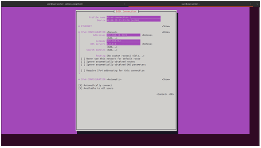
Figure 1: Network Configuration Topology
The configuration applied to each node is detailed below. Note that all nodes were configured with a /16 subnet mask to communicate with the gateway (192.168.0.1).
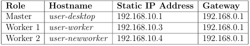
Table 1: Cluster Static IP Allocation
The configuration procedure using nmtui involved:
- Running nmtui in the
- Selecting ”Edit a connection” → ”Wired connection 1”.
- Changing IPv4 configuration from Automatic to Manual.
- Entering the designated IP (e.g., 168.10.3/24) and Gateway (192.168.0.1).
- Setting DNS servers to Google’s public DNS (8.8.8.8) to resolve external
2.4 Resource Optimization
To maximize the limited resources available on the Jetson Nano (4GB RAM) for the image processing workloads, the following optimizations were performed:
Disabling the GUI The graphical user interface (desktop environment) consumes significant memory(about 1.5GB). The system was configured to boot into headless mode (CLI only).
sudo s ys te m c t l set−d e f a u l t multi−user . ta r g e t
High-Performance Mode To ensure consistent processing speeds during the workload execution, the device was forced into maximum performance mode, locking the CPU and GPU clocks to their maximum frequencies.
sudo nvpmodel −m 0
Disabling Swap Kubernetes requires swap memory to be disabled for the scheduler to function correctly. This requirement is mainly to prevent thrashing as the access to secondary storage in painfully slow.
sudo swapoff −a
2.5 Container Runtime Configuration
Before initializing the cluster, the system packages were updated, and user permissions were adjusted to allow Docker management without root privileges.
sudo apt−get update && sudo apt−get upgrade −y
sudo groupadd docker
sudo usermod −aG docker $USER
newgrp docker
Finally, the nodes were rebooted to apply the headless configuration and hostname changes.
sudo s ys te m c t l reboot
III.KUBERNETES CLUSTER IMPLEMENTATION
3.1 Prerequisites Check
Before installing the orchestration layer, it was verified that all nodes had swap disabled and that the NVIDIA Docker runtime was active. This ensures that the pods scheduled by Kubernetes can access the underlying GPU hardware. To verify the GPU access from Docker containers, NVIDIA’s ”devicequery” container was used.
docker run −i t j i tte a m / devicequery . / device Query
For each node, if the setup is correct and GPU is accessible, ”Result = PASS” is displayed at the end of the output of the previous command.
3.2 Master Node Setup
The K3s (lightweight Kubernetes) distribution was chosen for its low resource footprint. The master node was initialized using the installer script. Note that the –docker flag is used to force K3s to utilize the Docker daemon configured in the previous section, rather than its default contained runtime.
c u r l −sf L https : // get . k3 s . i o
3.3 Worker Node Setup
To initialize the worker nodes, we first need to retrieve the unique node token from the master node. This token ensures secure communication between the control plane and the workers.
sudo cat / var / l i b / rancher / k3 s / s e r ve r / node−token
Using the token retrieved above, executing the following command on each worker node to join it to the cluster:
c u r l −sf L https : // get . k3 s . i o | K3S URL=h ttps :// <MASTER IP>:6443 K3S TOKEN=<
Configuring Node Roles
By default, the master node in K3s acts as both a control plane and a worker. To prevent the master node from being overloaded with workloads (which causes overheating and resource contention), we apply a taint. This ensures the master node is dedicated solely to scheduling and cluster management, rather than executing pod workloads.
# Taint the master node to prevent scheduling user pods on it
kubectl taint nodes <MASTER_NODE_NAME> node-role.kubernetes.io/master=true:NoSchedule
To ensure pods are scheduled correctly on the available compute resources, we assign specific labels to the worker nodes. This allows us to target deployments using node selectors.
kubectl label nodes user−worker node−type=worker
kubectl label nodes user node−type=worker
kubectl label nodes user−newworker node−type=worker
3.4 Setup Verification
The primary objective of the first workload was to validate the functional status of the GPU on every worker node simultaneously. Before attempting complex networked storage solutions, it was necessary to confirm that the container orchestration layer could successfully schedule pods that utilize the underlying NVIDIA hardware acceleration.
This workload performs parallel image classification using a pre-trained ResNet-50 model. Instead of fetching data from a central server, each node generates synthetic ”dummy” images locally, processes them, and logs the throughput.
4.1 Application Logic
The core application is a Python script utilizing PyTorch and Torchvision. The script is designed to be ”index-aware,” meaning it adjusts its workload based on an environment variable assigned by Kubernetes.
Key Logic Implementation:
- Model Loading: A pre-trained ResNet-50 model is loaded into the GPU memory (.cuda()) in evaluation mode.
- Job Partitioning: The script reads the JOB COMPLETION INDEX environment vari- able. This index (0, 1, or 2) allows the script to calculate a unique range of images to process, ensuring logical separation even though the data is generated
- Inference Loop: Random RGB images (224×224 pixels) are generated in memory, normalized, and passed through the neural network.
4.2 Containerization and Distribution Strategy
To ensure compatibility with the Jetson Nano’s ARM64 architecture and Tegra GPU drivers, the application was containerized using the NVIDIA L4T (Linux for Tegra) base image.
FROM nvcr . i o / nvidia / l 4 t −pytorch : r 32 . 7 . 1 − pth1 .10 −py3 WORKDIR /app
RUN pip 3 i n s t a l l Pillow ==8.2.0
# Pre−download the ResNet50 model to avoid runtime network dependencies
RUN python3 −c ” import – torch ; – import – t o r c h v i s i o n . models – as – models ; – models . COPY p ro c e s s im a g e s . py /app/
CMD [ ” python3 ” , ” p ro c e s s im a g e s . py” ]
4.2.1 Image Distribution Workflow
Since the cluster operated on a private network without a local container registry, a manual distribution strategy was employed to ensure all worker nodes had access to the exact same image.
- Build: The image was built on the Master
docker build −t jetson −i n f e r e n c e : v1 .
- Export: The image was saved to a compressed
docker save jetson −i n f e r e n c e : v1 | gzip > jetson −i n f e r e n c e . ta r . gz
- Transfer: The tarball was transferred to each worker node using
scp jetson −i n f e r e n c e . ta r . gz user@192 . 1 6 8 . 1 0 . x : / home/ user /
- Import: On each worker node, the image was loaded into the local Docker docker
load < jetson −i n f e r e n c e . ta r . gz
4.3 Orchestration Configuration
The workload was deployed as a Kubernetes Job rather than a Deployment. This ensures the pods run to completion (finite task) rather than restarting indefinitely.
Key YAML Configurations:
• parallelism: 2 and completions: 2: Specifies that 2 pods should run, and they should run simultaneously (one for each worker).
• completionMode: Indexed: This injects the JOB COMPLETION INDEX environment variable into each pod, allowing the Python script to identify which worker it is running on.
• nodeSelector: Targets only nodes labeled worker, preventing execution on the master node.
apiVersion: batch/v1
kind: Job
metadata:
name: inference-parallel
spec:
completions: 2
parallelism: 2
completionMode: Indexed
template:
spec:
restartPolicy: Never
nodeSelector:
node-type: worker
containers:
-name: inference
image: jetson-inference:v1
imagePullPolicy: Never
env:
-name: TOTAL_JOBS
value: “2”
-name: TOTAL_IMAGES
value: “120”
4.4 Verification of GPU Access
The job was applied to the cluster using kubectl apply -f job-parallel.yaml. Verification was performed by checking the logs of the completed pods.
The presence of the execution logs confirming model loading and inference throughput verified that the NVIDIA Container Runtime was correctly passing GPU capabilities to the Kubernetes pods on all three worker nodes.
V.NETWORK FILE SYSTEM (NFS) INTEGRATION
5.1 Overview
Network File System (NFS) provides a centralized storage solution for the Kubernetes cluster, enabling persistent volume claims across worker nodes. With k3s operational on all Jetson nodes, NFS configuration represents the final infrastructure component required for stateful application deployment.
5.2 Prerequisites
The implementation assumes:
- Functional k3s cluster with one master node (192.168.10.1) and multiple worker nodes
- Ubuntu-based operating system on all Jetson devices
- Network connectivity verified between master and worker nodes
- nfs-common package installed on all worker nodes
5.3 NFS Server Configuration on Master Node
The master node serves as the NFS server, exporting the /nfs/images directory to the cluster subnet. First create /nfs/images directory and modify its permissions and allow both read and write to it from all nodes.
sudo mkdir −p / n f s / images
sudo chown nobody : nogroup / n f s / images sudo chmod 777 / n f s / images
The exports are then configured for any worker node to access the shared nfs folder.
For this, the following is added to the end of /etc/exports
/nfs/images 192.168.10.0/24(rw,sync,no_subtree_check,no_root_squash)
Then, the export configuration can be applied and the nfs server be restarted to load the applied changes.
sudo e xp o r t f s −ra
sudo s ys te m c t l r e s t a r t nfs −kernel −s e r ve r
5.4 Worker Node Configuration
Each worker node requires the NFS client utilities to mount the shared volume. Install
nfs-common on all worker nodes:
sudo apt i n s t a l l −y nfs −common
To test mounting capability before Kubernetes deployment:
sudo mkdir −p /tmp/ nfs −t e s t
sudo mount −t n f s 1 9 2 . 1 6 8 . 1 0 . 1 : / n f s / images /tmp/ nfs −t e s t
On all worker node, the shared /nfs/images directory must be visible and any changes applied must also be visible to all nodes. This verifies that the NFS is working correctly.
5.5 Persistent Volume and Claim Definition
The Kubernetes PersistentVolume (PV) and PersistentVolumeClaim (PVC) are defined statically to ensure predictable storage allocation. The PV specification includes mount options optimized for reliability.
apiVersion: v1
kind: PersistentVolume metadata:
name: nfs-images-pv spec:
capacity:
storage: 5Gi accessModes:
– ReadOnly
Many persistentVolumeReclaimPolicy: Retain
mountOptions:
– hard nfs:
server: 192.168.10.1 path: “/nfs/images”
apiVersion: v1
kind: PersistentVolumeClaim
metadata:
name: nfs-images-pvc spec:
accessModes:
– ReadOnlyMany
storageClassName: “”
volumeName: nfs-images-pv
resources:
requests:
storage: 5Gi
5.6 Deployment and Verification
Apply the configuration and verify successful binding:
sudo k3 s kubectl apply −f nfs −images−pv−pvc . yaml
sudo k3 s kubectl get pv , pvc
The PVC status should transition to Bound. If the PVC remains Pending, inspect events for mount errors:
sudo k3 s kubectl d e s c r ib e pvc nfs −images−pvc
5.5 Persistent Volume and Claim Definition
Deploy a test pod to validate volume mounting:
apiVersion: v1 kind: Pod metadata:
name: nfs-test-pod spec:
containers:
name: test image: busybox
command: [“/bin/sh”, “-c”, “ls -la /mnt && sleep 3600”] volumeMounts:
name: nfs-storage mountPath: /mnt volumes:
name: nfs-storage persistentVolumeClaim:
claimName: nfs-images-pvc
The logs of each node show the contents of the /nfs/images/ directory listed. This confirms that the NFS is accessible by all nodes.
VI.WORKLOAD II: DISTRIBUTED IMAGE PROCESSING VIA NFS
Building upon the successful GPU validation in Workload I, the second workload represents a realistic edge computing scenario. In this configuration, the dataset is centralized on the Master node and exposed via the Network File System (NFS). The worker nodes must fetch images over the network, process them using the GPU, and report the results.
This setup introduces network I/O latency as a variable, distinguishing it from the purely computational Workload I.
6.1 Application Logic
The application logic was modified to handle file system operations. A Python script (process nfs.py) was developed to integrate with the Kubernetes Indexed Job mecha- nism.
Key Implementation Details:
- Dynamic File Listing: The script uses the glob library to list all JPEG files in the mounted
- Index-Based Partitioning: Similar to Workload I, the JOB COMPLETION INDEX is used to slice the file list. If there are 1200 images and 3 workers, Worker 0 takes indices 0-399, Worker 1 takes 400-799, etc.
- GPU Warm-up: A dummy inference pass is performed before the timer starts. This ensures that the initialization time of CUDA context creation does not skew the throughput metrics.
- Error Handling: A try-catch block is included inside the loop to ensure that a single corrupt image file does not crash the entire container.
import torch
import t o r c h v i s i o n . models as models
import t o r c h v i s i o n . transforms as transforms
from PIL import Image
import time import os import glob
# Load model
model = models . re s n e t 5 0 ( p re t ra in e d=True ) . cuda ( ) . eval ()
p re p ro c e s s = transforms . Compose ( [ transforms . Resize ( 2 5 6 ) ,
transforms . CenterCrop ( 2 2 4 ) , transforms . ToTensor ( ) ,
transforms . Normalize ( mean =[ 0 . 485 , 0 . 4 5 6 , 0 . 4 0 6 ] ,
std =[ 0 . 229 , 0 . 2 2 4 , 0 . 2 2 5 ] ) ,
] )
# Get job index from environment
jo b in d e x = int ( os . getenv ( ’JOB COMPLETION INDEX ’ , ’ 0 ’ )) t o t a l j o b s = int ( os . getenv ( ’TOTAL JOBS ’ , ’ 1 ’ ))
# NFS mount path ( mounted v ia Persistent Volume in k 8 s )
nf s im a ge s pa th = os . getenv ( ’NFS IMAGES PATH ’ , ’ / n f s / images ’ )
# Get a l l image f i l e s from NFS
a l l im a g e s = sorted ( glob . glob ( os . path . j o i n ( nfs images path , ’ ∗ . jpg ’ ) ) ) to ta l im a g e s = len ( a l l im a g e s )
i f to ta l im a g e s == 0 :
raise Value Error ( f ”No – images – found – in – { nf s im a ge s pa th }” )
# Calculate image range f or t h i s job
im a g e s p e r jo b = to ta l im a g e s // t o t a l j o b s s t a r t i d x = jo b in d e x ∗ im a g e s p e r jo b
# Last job handles any remaining images
i f jo b in d e x == t o t a l j o b s − 1 : end idx = to ta l im a g e s
else :
end idx = s t a r t i d x + im a g e s p e r jo b
# Warm up GPU to exclude i n i t i a l i z a t i o n time from metrics
dummy = torch . randn ( 1 , 3 , 224 , 2 2 4 ) . cuda () model (dummy)
torch . cuda . synchronize ()
print ( f ” Job – { jo b in d e x } : – Pro ce s s ing – images – { s t a r t i d x } – to – { end idx −1}” )
print ( f ” Total – images – a v a i l a b l e : – { to ta l im a g e s }” )
# Process images from NFS
s t a r t t im e = time . time () pro ce s s e d co unt = 0
for i in range ( s t a r t id x , end idx ) :
try :
# Load image from NFS
img path = a l l im a g e s [ i ]
img = Image . open ( img path ) . convert ( ’RGB’ )
img tensor = p re p ro c e s s ( img ) . unsqueeze ( 0 ) . cuda ()
with torch . no grad ( ) :
output = model ( img tensor ) pro ce s s e d co unt += 1
except Exception as e :
print ( f ” Error – p r o c e s s in g – image – { i } : – { e }” )
continue
torch . cuda . synchronize ()
e laps e d = time . time () − s t a r t t im e
print ( f ” Job – { jo b in d e x } – completed : – { pro ce s s e d co unt } – images – in – { e laps e d : . 2 f
print ( f ” Throughput : – { pro ce s s e d co unt / e laps e d : . 2 f } – images / s e c ” )
VII.PERFORMANCE ANALYSIS
To evaluate the efficiency of the cluster, we benchmarked the system using the NFS-based ResNet50 workload. We compared the performance of running the workload on a single Jetson Nano versus distributing it across the three-node cluster.
7.1 Experimental Setup
- Dataset: 1,200 JPEG images (Shared via NFS).
- Model: ResNet50 (Pre-trained).
- Power Mode: All nodes set to 10W (MAXN) mode with jetson clocks
- Metric: End-to-end execution time (including network file fetch and GPU inference).
7.2 Results
7.2.1 Scenario A: Single Node Execution
In this baseline scenario, a single worker node processed the entire dataset of 1,200 images sequentially.
- Total Images: 1,200
- Total Time: 150 seconds
- Effective Throughput: 8 images/sec
7.2.2 Scenario B: Cluster Execution (3 Nodes)
In the distributed scenario, the dataset was split evenly, with each of the three worker nodes processing 400 images in parallel.
- Total Images: 1,200 (400 per node)
- Max Execution Time (Slowest Node): 99 seconds
- Aggregate Throughput: 12 images/sec
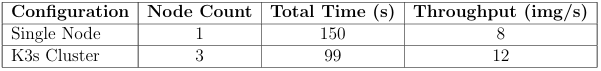
Table 2: Performance Comparison: Single Node vs. Distributed Cluster
7.3 Speedup and Overhead Analysis
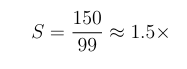
The theoretical speedup for a 3-node cluster is 3×. However, in practice, overheads such as network latency and orchestration delays reduce this factor.
The speedup was calculated using the formula:
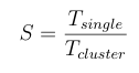
Substituting our measured values:
7.3.1 Observations
- Network Bottleneck: Unlike local storage, the workers requested images simultaneously from the Master node over the This likely introduced I/O latency, as all three nodes competed for the Master’s network bandwidth.
- Load Balancing: The difference in execution time between the fastest and slowest worker was negligible, indicating that the static partitioning strategy (Total/N ) was effective for this uniform dataset.
- Efficiency: While we did not achieve a perfect 2× linear speedup due to the NFS overhead, the cluster demonstrated a significant reduction in total processing time, proving the viability of distributed edge.
VIII.CHALLENGES AND TROUBLESHOOTING
• Hostname Setup Issues: Initially, we used the default hostname(user-desktop) while setting up Jetson Nano. This caused the master node to reject connection of other Nodes to the cluster, as the hostname were same, which caused an authentication error.
• Static IP: We were using the default CIDR of 10.42.0.1/24 on our laptop’s ethernet interface to share internet with the nodes. This CIDR collided with the kubernetes’ default CIDR for pod creation, which resulted in networking not working when k3s starts up.
• All pods as master node: In our initial setup, we misconfigured all our nodes as master nodes, causing them to fail to join the cluster. The simple fix was to install k3s-agent on the worker nodes, which made them behave as worker nodes.
• Versioning error with NFS: The latest Jetpack OS for Jetson Nano(4.6) uses Ubuntu 18.04 . This caused some versioning error when we were trying to use a newer version of NFS.
• Waiting for GPU resource: For some reason, our Jetson boards were not advertising the availability of a GPU, although we could access the GPUs from the jobs. To fix this, we just changed our launch yaml file to not require a node to advertise a GPU before scheduling a GPU workload to it. The docker container configuration already handles the availability of GPU to our containers(See 2.5).
• Tainting the Master: We allowed master to be a schedulable node initially. This caused our master node jetson to thermal throttle and slow down everything(scheduling other nodes and working as too much for a Jetson Nano). So, we added a taint to the master node to not schedule any pods on it, using it only for scheduling of worker nodes.
• Slower Node: Our main aim was to build a cluster of 4 Jetson Nano(1 master and 3 workers). But one of our worker nodes was significantly slower that other nodes(at times, 10x slower). We could not find the reason as to why this was the case, thus we did not use that node in our cluster while benchmarking.
Recent Comments