
I.OBJECTIVE
This course project consists of two parts demonstrating embedded system design:
Part A: Demonstrate runtime FPGA reconfiguration by designing and switching between two hardware overlays (XOR checksum and CRC32) on PYNQ-Z2. Process network packets using hardware acceleration and compare performance with software implementations to understand hardware-software trade-offs in heterogeneous computing.
Part B: Create a complete bootable PetaLinux image for Zynq-7000 SoC from scratch, covering the entire workflow from Vivado hardware design through Linux kernel compilation to SD card deployment, demonstrating embedded Linux development for FPGA-based systems.
II.PLATFORM
Hardware: PYNQ-Z2 (Zynq-7000 XC7Z020)
OS: PYNQ Linux (Ubuntu 18.04)
Tools: Vivado 2020.2, Python 3.8
Network: Ethernet 192.168.2.99
Clock Frequencies: ARM Cortex-A9 PS @ 650 MHz, FPGA Fabric @ 100 MHz (FCLK CLK0)
III.PART A: FPGA HARDWARE DESIGN
3.1 System Architecture
Zynq-7000 SoC integrates ARM Cortex-A9 processors (Processing System) with programmable logic fabric. Communication occurs via AXI4-Stream protocol through DMA controllers. Two independent bitstreams (design 1.bit for XOR, design 2.bit for CRC32) share identical AXI interfaces but implement different algorithms.
3.2 PS-PL Integration and Clock Domains
The Processing System operates at 650 MHz while the Programmable Logic runs at 100 MHz (6.5x slower). This clock difference is critical for understanding performance. The AXI interconnect handles clock domain crossing between PS and PL. Data transfers occur through AXI HP0 (High Performance) port providing 32-bit or 64-bit wide paths. The slower FPGA clock limits throughput but enables complex logic implementation. For simple operations like XOR, the PS running at 650 MHz can outperform PL at 100 MHz due to clock advantage and DMA overhead.
3.3 Design 1: XOR Checksum
Simple XOR-based error detection performing bitwise XOR across all 32-bit packet words. Hardware performs: Checksum = D0 ⊕ D1 ⊕ … ⊕ Dn−1. Implementation uses passthrough architecture: input data streams through while accumulating XOR in a register. After receiving TLAST signal, module appends computed checksum as final output word. Two-state FSM: passthrough (compute XOR) and send checksum (output result).
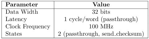
Table 1: XOR Design Specifications
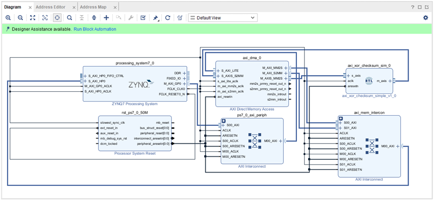
Figure 1: Block Design with AXI based XOR RTL Module
3.4 Design 2: CRC32
IEEE 802.3 CRC32 using polynomial 0x04C11DB7. Bit-serial implementation using combinatorial function that processes all 32 bits of input word in one clock cycle (unrolled loop). Initialized to 0xFFFFFFFF, final result inverted per IEEE standard. Same passthrough architecture as XOR but with CRC calculation function. More complex computation but still single-cycle per word due to combinatorial logic.
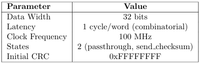
Table 2: CRC32 Design Specifications
3.5 AXI Interface
Both designs use AXI4-Stream with 32-bit data width. DMA controller manages data transfer between processor memory and FPGA fabric via AXI HP0 port.
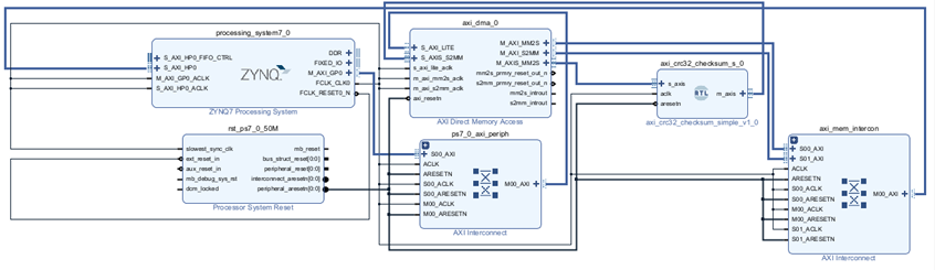
Figure 2: Block Design with AXI based CRC RTL Module
IV.PART B: SOFTWARE AND OS INTERACTION
4.1 Operating System
PYNQ runs Ubuntu 18.04-based Linux on ARM cores at 650 MHz. Kernel includes FPGA Manager for bitstream loading and exposes hardware through /dev/mem for memory-mapped IO access.
4.2 Overlay Class and IP Dictionary
When PYNQ loads an overlay, it parses the .hwh file to build an IP dictionary (ip dict) containing all hardware blocks and their base addresses. Each IP block becomes a Python object accessible via overlay attributes. Example: overlay.axi dma 0 provides access to DMA controller. The ip dict maps IP names to physical addresses, register offsets, and memory ranges.
4.3 Memory-Mapped IO (MMIO)
PYNQ uses direct MMIO instead of kernel drivers. Process: Vivado assigns physical addresses (e.g., 0x40400000 for DMA) → .hwh file stores address map → PYNQ Overlay class parses .hwh → creates MMIO objects using mmap() on /dev/mem → Python code accesses hardware registers through MMIO.read()/write() methods. No custom kernel drivers needed.
4.4 Address Translation and AXI Access
Physical addresses from Vivado map directly to processor’s address space through AXI interconnect. When Python writes to overlay.axi dma 0 registers, the sequence is: Python MMIO object → virtual address → MMU translates to physical address → AXI HP0 port → AXI interconnect routes to DMA at 0x[Address] → DMA performs transaction. The ip dict enables Python to access any IP block by name without knowing physical addresses.
4.5 Data Transfer via DMA and IP Dict
To send packet data to FPGA: (1) Allocate physically contiguous buffer using pynq.allocate() from CMA, (2) Copy packet into buffer, (3) Access DMA through overlay.axi dma 0 (resolved from ip dict), (4) Call sendchan-nel.transfer(buffer) which programs DMA registers with buffer’s physical address, (5) DMA reads memory and streams to custom IP via AXI Stream, (6) Result returns through recvchannel.transfer(). The ip dict abstraction allows seam-less hardware access—Python code doesn’t manipulate addresses directly.
4.6 Dynamic Overlay Switching
Runtime bitstream loading via PCAP (Processor Configuration Access Port). PYNQ Overlay class loads .bit file through kernel FPGA Manager. Observed switchover time: 1.5-2.5 seconds (includes bitstream programming and IP dict reconstruction). Completely reconfigures fabric—all state lost. Application switches between XOR and CRC32 every 60 seconds.
4.7 Timing Measurement
Both hardware and software processing times measured using Python’s time.time() function from the time module. This provides wall-clock time with microsecond resolution through system calls to Linux kernel’s high-resolution timers. Measurement sequence: record start time = time.time() → perform operation → record end time = time.time() → compute delta = (end time – start time) * 1e6 for microseconds. For hardware: includes DMA setup, data transfer to PL, computation, and transfer back. For software: pure CPU computation time without IO overhead.
4.8 Performance Results and Analysis
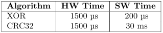
Table 3: Processing Latency per Packet (98 bytes)
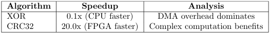
Table 4: Hardware Acceleration Results
XOR Performance: CPU faster than FPGA despite hardware acceleration. Reason: (1) ARM cores at 650 MHz vs FPGA at 100 MHz (6.5x clock advantage), (2) XOR is trivial operation—single CPU instruction, (3) DMA overhead (setup, memory copy, AXI transfer) takes 280µs while CPU computes XOR in 28µs. Hardware acceleration counterproductive for simple operations.
CRC32 Performance: FPGA achieves 17x speedup. Reason: (1) CRC32 requires extensive bit manipulation and branching in software ( 4850µs), (2) Hardware implements unrolled combinatorial logic processing 32 bits in one 100MHz cycle, (3) DMA overhead ( 285µs) now small compared to software time, (4) Parallel hardware execution overcomes clock disadvantage. Complex algorithms justify hardware acceleration.
Clock Domain Impact: PS runs 6.5x faster than PL. For operations completing in few cycles, PS wins. For operations requiring many cycles or complex logic, PL’s parallelism compensates for slower clock. This demonstrates hardware-software trade-off in heterogeneous computing.
4.9 Testing
Generated ping packets from laptop to PYNQ board. Processed 245 packets across 4 overlay switches (each switch taking 1.5-2.5 seconds). 100% match rate between hardware and software calculations. No packet corruption during switching.
V.CONCLUSION
5.1 Part A Summary
Successfully demonstrated dynamic FPGA reconfiguration with two packet processing overlays. PYNQ’s MMIO and IP dictionary approach enables hardware access without kernel drivers by mapping physical addresses through /dev/mem.
Key Findings: (1) XOR: CPU 10x faster than FPGA—DMA overhead exceeds computation benefit when PS runs at 650 MHz vs PL at 100 MHz. Simple operations don’t justify hardware acceleration. (2) CRC32: FPGA 17x faster—complex computation overcomes DMA overhead and clock disadvantage. (3) Switchover time: 1.5-2.5 seconds for complete bitstream reconfiguration and IP dict rebuild.
Observation: Hardware acceleration effectiveness depends on computation complexity relative to data transfer overhead and clock domain differences. Time-multiplexing FPGA resources demonstrated through runtime bitstream switching.
PART B: PETALINUX BOOTABLE IMAGE CREATION
VI.INTRODUCTION
PetaLinux is an embedded Linux Software Development Kit (SDK) targeting FPGA-based system-on-a-chip (SoC) designs or FPGA designs. PetaLinux tools is a collection of PetaLinux source, scripts, programs and documentation for implementing and building PetaLinux on Xilinx AMD FPGAs.
This document provides a comprehensive workflow for creating bootable SD card images for Zynq-7000 FPGA boards (specifically PynqZ2) using PetaLinux in a VMware Ubuntu environment. The workflow covers hardware design creation in Vivado, PetaLinux project setup, build process, and final SD card deployment.
6.1 Environment Overview
- Host OS: Windows with VMware Workstation Pro
- Guest OS: Ubuntu 04 LTS
- Target Hardware: PynqZ2 Board (Zynq-7020 FPGA)
- Tools: Vivado 2, PetaLinux 2024.2
- Goal: Create bootable SD card images for embedded Linux development
VII.SECTION A : VIVADO HARDWARE DESIGN AND XSA GENERATION
The first phase involves creating the hardware design in Vivado that will serve as the foundation for the PetaLinux software development.
7.1 Hardware Design Workflow
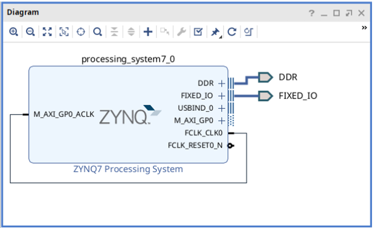
Figure 3: Block Design
1.Open Vivado
• Launch Vivado Design Suite for FPGA hardware design
2.Create new PynqZ2 project in Home folder
• Initialize new Vivado project targeting PynqZ2 board (Zynq-7020 FPGA)
• Set project location in Home directory
• This folder will contain the PetaLinux project in subsequent steps
3.Add Zynq Processing System IP
• Insert Zynq PS (Processing System) block containing ARM Cortex-A9 processor and peripherals
4.Run Connection Automation
• Automatically connects essential Zynq PS interfaces
• DDR: External memory controller connections
• Fixed IOs: MIO (Multiplexed I/O) pins for basic board functionality
• Creates proper connections for processor operation
5.Complete required hardware design
• Finalize block design with necessary IP blocks and connections for target application
6.Create HDL Wrapper
• Generates top-level Verilog/VHDL wrapper around the block design for synthesis
7.Generate Bitstream
•Synthesize, implement, and generate FPGA configuration file (.bit)
8.Export Hardware
• Path: File → Export → Export Hardware → Next → Select ”Include Bitstream” → Finish
• Creates .XSA (Xilinx Support Archive) file containing hardware description for PetaLinux
7.2 Design wrapper.XSA:
- XSA (Xilinx Support Archive): Hardware description package that bridges Vivado hardware design with PetaLinux software development
- design wrapper: Top-level HDL wrapper name automatically generated around the block design
Contents inside design wrapper.XSA: Block design files (.bd), IP configurations, memory maps, bitstream (.bit), device tree information, Zynq PS settings, peripheral drivers, interrupt mappings, clock configurations, pin assignments, project constraints
Result: .XSA file generated in Vivado project directory, ready for PetaLinux hardware description import in Section B.
VIII.SECTION B: PETALINUX PROJECT CREATION AND BOOT IMAGE GENERATION
This section covers the complete PetaLinux workflow from environment setup to SD card deployment.
8.1 Step 1: Install PetaLinux Dependencies
First, install the essential build tools and dependencies required before PetaLinux installation.

Listing 1: Installing PetaLinux Dependencies
Package explanations:
- build-essential: Core compilation tools (gcc, g++, make, dpkg-dev) for building software from source
- gcc-multilib: Multi-architecture support for GCC compiler – builds 32-bit and 64-bit binaries
- xterm: Terminal emulator required by PetaLinux tools for graphical configuration menus
- autoconf: Automatic configure script builder for software compilation
- libtool: Generic library support script for building shared libraries
- texinfo: Documentation system for processing .texi files into various formats
- zlib1g-dev: Development files for zlib compression library for handling compressed files
- libncurses-dev: Development files for ncurses library providing text-based user interface capabilities
8.2 Step 2: PetaLinux Installation
Install PetaLinux in the home directory instead of system folder for better user control and permissions.

Listing 2: PetaLinux Installation
command explanations:
- ls: Lists current directory contents to verify installer file is present
- mkdir /petalinux: Creates dedicated ’petalinux’ directory in user’s home folder
- ./petalinux-installer.run –dir /petalinux/: Executes installer with custom directory specification
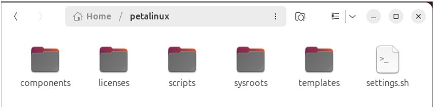
Figure 4: PetaLinux Tools
8.3 Step 3: Environment Configuration
Configure PetaLinux environment variables and make them permanently accessible.
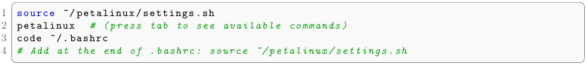
Listing 3: Environment Setup
command explanations:
- source /petalinux/settings.sh: Loads PetaLinux environment variables into current terminal session
- petalinux + tab: Tests auto-completion to verify PetaLinux commands are available
- code /.bashrc: Opens bash configuration file in VS Code for permanent setup
- Manual step: Add source command to .bashrc for automatic loading in new terminals
Note: Since this is a dedicated VM for FPGA development, modifying .bashrc globally is safe and convenient.
8.4 Step 4: PetaLinux Project Creation
Create a PetaLinux project inside the Vivado project folder and configure it with hardware description.
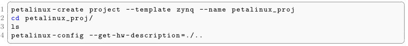
Listing 4: PetaLinux Project Creation
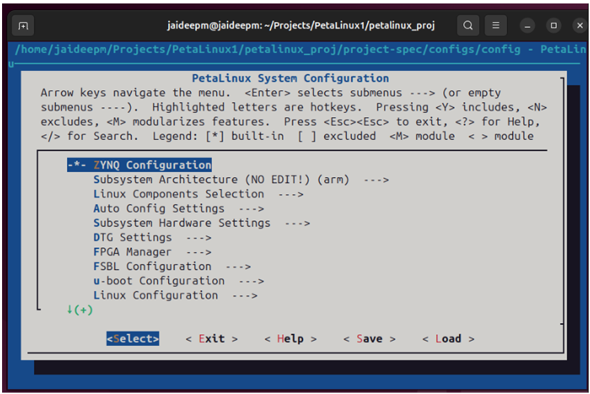
Figure 5: PetalLinux Config Window
Command explanations:
- petalinux-create: Creates new PetaLinux project using Zynq template for PynqZ2 board (Zynq-7000 series)
- –template zynq: Uses Zynq SoC template with ARM Cortex-A9 processor
- –name petalinux proj: Names the project folder as ”petalinux proj”
- cd petalinux proj/: Navigates into newly created project directory
- ls: Lists project structure contents to verify creation
- petalinux-config –get-hw-description=./..: Configures project with hardware description from parent directory where .xsa file is located
Result: Configuration window opens for hardware-specific settings for PynqZ2 board setup.
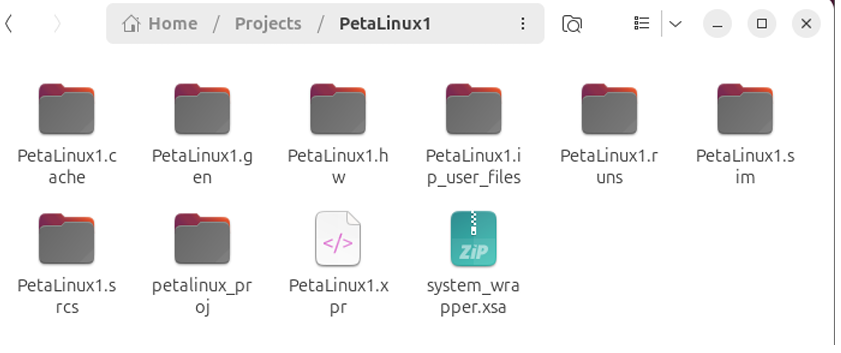
Figure 6: Petalinux1 (Vivado Project) with newly created petalinuxproj folder
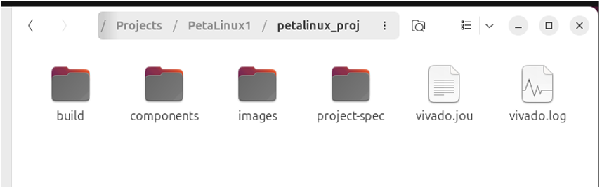
Figure 7: Petalinux Project Folder
8.5 Step 5: Build Process and Error Resolution
Build the PetaLinux project and resolve common Ubuntu/VM-related build errors.
![]()
Listing 5: PetaLinux Build Process
Explanation: Builds the entire PetaLinux project (kernel, rootfs, bootloader, device tree)
8.5.1 Common Build Errors and Solutions
Error 1: libtinfo.so.5 missing
![]()
Listing 6: Fix libtinfo Library Issue
Explanation: Creates symbolic link for missing libtinfo library. PetaLinux tools expect libtinfo.so.5 but Ubuntu 24.04 has libtinfo.so.6. Creates compatibility link so older tools can find the library.
Error 2: AppArmor permission denied
![]()
Listing 7: Fix AppArmor Restriction
Explanation: Disables AppArmor security restriction for unprivileged user namespaces. AppArmor blocks PetaLinux from accessing /proc/self/uid map. This command removes the restrictive security profile and allows PetaLinux build tools to create necessary namespaces.
Rebuild after fixes:

Listing 8: Successful Build
Result: Build completes successfully. The images/linux/ directory contains generated build artifacts including boot files (BOOT.BIN, boot.scr), Linux kernel (image.ub), root filesystem (rootfs.tar.gz), and device tree files (system.dtb).
8.6 Step 6: SD Card Preparation
Set up SD card with proper partitions for PynqZ2 board boot and root filesystem.

Listing 9: SD Card Partitioning
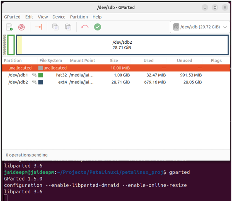
Figure 8: GParted Software
[H] Command explanations:
• sudo apt install gparted: Installs GParted disk partitioning tool with graphical interface
• gparted: Launches GParted partition manager application
Manual partitioning steps:
1.Select SD card from dropdown menu – choose correct storage device
2.Right-click → Delete all existing partitions – removes any existing partition table
3.Create Boot Partition (Partition 1):
• Type: New partition
• File system: FAT32
• Free space preceding: 10 MiB
• Size: 1024 MB (1 GB)
• Purpose: Stores boot files (BOOT.BIN, kernel, device tree)
4.Create Root Filesystem Partition (Partition 2):
• Type: New partition
• File system: ext4
• Size: Remaining SD card capacity
• Purpose: Contains Linux root filesystem, user programs, configuration files
5. Apply changes and close GParted
Result: SD card has two partitions: 1.1 GB FAT32 (boot partition) and remaining capacity ext4 (Linux root filesystem).
8.7 Step 7: Boot Image Generation and Deployment
Generate the final boot image and deploy all files to SD card partitions.

Listing 10: Boot Image Generation
Explanation: Packages bootloader components into a single BOOT.BIN file by combining zynq fsbl.elf (First Stage Boot Loader), u-boot.elf (U-Boot bootloader), and system.dtb (Device Tree Binary – hardware description) to create BOOT.BIN file required for Zynq boot sequence.
Copy boot files to FAT32 boot partition:

Listing 11: Deploy Boot File
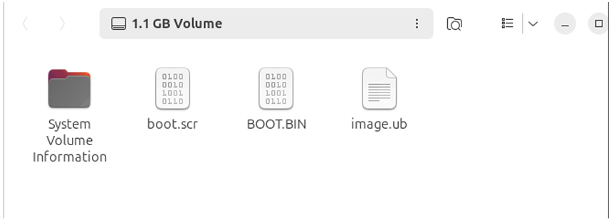
Figure 9: Boot partition (fat32)
File explanations:
• BOOT.BIN: Combined bootloader package containing all necessary boot components
• image.ub: Linux kernel image in U-Boot format
• boot.scr: Boot script with boot sequence commands
• /media/jaideepm/0F09-9B5A: Auto-mounted FAT32 boot partition location
Deploy root filesystem to ext4 partition:
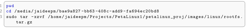
Listing 12: Deploy Root Filesystem
command explanations:
- pwd: Print working directory to verify current location
- cd /media/…: Navigate to auto-mounted ext4 Linux root partition
- tar -xzvf: Extract root filesystem archive to SD card
- -x: Extract files from archive
- -z: Handle gzip compression
- -v: Verbose output (show files being extracted)
- -f: Specify archive filename
rootfs.tar.gz: Compressed root filesystem containing Linux system files, libraries, and user space
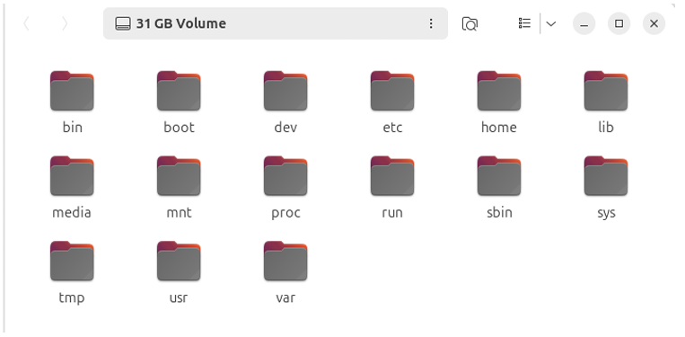
Figure 10: Root Filesystem Partition (ext4)
8.8 Step 8: Serial Console Connection and Boot
Establish serial communication with PynqZ2 board and complete the first boot.

Listing 13: Serial Console Setup
Command explanations:This workflow provides
- ls /dev/ttyUSB*: Lists all USB serial devices to identify board’s serial port
- minicom -D /dev/ttyUSB1 -b 115200: Opens serial terminal connection
- -D /dev/ttyUSB1: Specifies the serial device (USB1 identified from previous step)
- -b 115200: Sets baud rate to 115200 (standard for PynqZ2)
Hardware setup and final boot:
- Insert SD card into PynqZ2 board
- Set jumper pin to SD card boot mode on PynqZ2
- Power on PynqZ2 board
- Monitor boot process through serial console:
- Observe FSBL (First Stage Boot Loader) execution
- Watch U-Boot initialization messages
- Monitor Linux kernel boot sequence
- See root filesystem mounting
- Login with username: petalinux (default username)
- Set new password and confirm for security
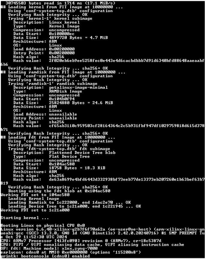
Figure 11: UART Terminal Print during bootup
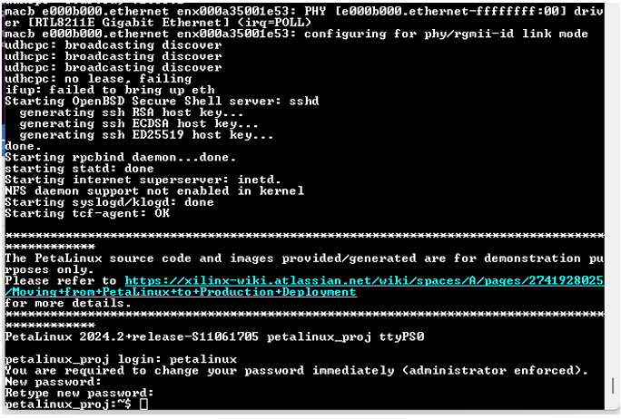
Figure 12: UART Terminal Print during bootup
Result: PynqZ2 board successfully boots custom PetaLinux image from SD card with full Linux console access. The boot image creation workflow is complete and the system is ready for embedded development.
IX.CONCLUSION
This workflow provides a methodology for creating bootable PetaLinux images for Zynq-7000 FPGA development. The process encompasses hardware design creation in Vivado, PetaLinux environment setup, project configuration, build process, and final SD card deployment.
9.1 Key Achievements
-
- Successful VMware Ubuntu environment setup for FPGA development
- Complete Vivado hardware design workflow with .XSA generation
- PetaLinux installation and environment configuration
- SD card partitioning and file system deployment
- Successful boot image generation and deployment
- Serial console connection and first boot completion
X.OVERALL CONCLUSION
This two-part project provided comprehensive experience in embedded system design for FPGA-based platforms, covering both runtime reconfiguration and bootable image creation.
10.1 Part A Achievements
Demonstrated dynamic partial reconfiguration capabilities of Zynq SoC with runtime bitstream switching. Analyzed hardware-software performance trade-offs, discovering that simple operations (XOR) perform better on 650 MHz ARM processor while complex algorithms (CRC32) benefit from dedicated FPGA logic despite slower 100 MHz clock. Implemented complete PYNQ-based system using MMIO for direct hardware access without kernel drivers.
10.2 Part B Achievements
Created complete bootable Linux system for Zynq-7000 from ground up using PetaLinux tools. Covered full workflow: Vivado hardware design with XSA generation, PetaLinux environment setup, kernel compilation, root filesystem creation, SD card partitioning, and successful boot deployment. Gained experience with embedded Linux development, bootloader configuration, and device tree management for FPGA-based SoCs.
XI.REFERENCES
- (2025). VMware Workstation Pro Download Free – 17.6.4 25H2. Available at: https://www.techspot.com/ downloads/5689-vmware-workstation.html
- Canonical (2025). Download Ubuntu Desktop. Available at: https://ubuntu.com/download/desktop
- (2025). Vivado Design Suite Downloads. Available at: https://www.xilinx.com/support/download.html
- (2025). PetaLinux Commands – PetaLinux Tools Documentation: Reference Guide (UG1144). Available at: https://docs.amd.com/r/en-US/ug1144-petalinux-tools-reference-guide
- (2025). PetaLinux Tools Downloads. Available at: https://www.xilinx.com/support/download/index.html/ content/xilinx/en/downloadNav/embedded-design-tools.html
- Ubuntu (2025). Comment #8: Bug #2056555: Bugs: apparmor package. Available at: https://bugs. launchpad.net/ubuntu/+source/apparmor/+bug/2056555/comments/8
- Digilent (2020). Vivado missing library error (libtinfo.so.5). Available at: https://forum.digilent.com/topic/ 21051-vivado-missing-library-error-libtinfoso5/
Recent Comments