
In TI Tiva LaunchPad, each of the Generator has two Compare registers. They are called PWMxCMPA (PWMx Compare A) and PWMxCMPB (PWMx Compare B). As the Counter counts down (or up), its value is compared with the PWMxCMPx register and upon a match, a PWM output pin will do one of the following:
- do nothing,
- toggle,
- driven HIGH,
- driven LOW
These output actions are not limited to the compare register, you may choose one of these actions when the counter reaches zero and when the counter reloads. The selections of these actions are made in the PWM generator (PWMxGENx) register. Each register is associated with an output pin and has six actions you may specify:
- action when the counter matches comparator B while counting down.
- action when the counter matches comparator B while counting up.
- action when the counter matches comparator A while counting down.
- action when the counter matches comparator A while counting up.
- action when the counter is reloaded.
- action when the counter reaches zero.
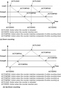
These options allow us to generate some elaborate output waveforms. Each wave generator has 2 outputs: PwmA and PwmB; Using PWMxGENA and PWMxGENB registers the action of the outputs are chosen as was shown in Figure 15-24. The details of PWMxGENx register is shown in Figure 15.31. Each event may cause an action specified by two bits.
Generating periodic square wave using down counting mode
For now, we will start with a simple periodic square wave. To do that, a PWMxGENx register is configured so that the output is driven high when the counter is reloaded and the output is driven low when the counter matches a comparator register while counting down. See Figure 15-42.
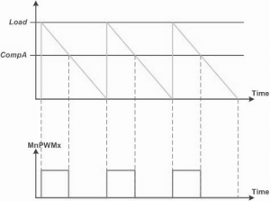
Figure 15.42: PWM generation using count-down mode and ComparatorA
The PWM Output Frequency in Count Down mode
To calculate the value for the PWMxLOAD register for a desired PWM output frequency, we divide the period of the desired PWM output by the period of the PWM module clock. Examples 15.41 and 15.42 show how to calculate the LOAD register value.
Example 15.41: Assume the PWM3 Module clock frequency is 8MHz. Find the value of the PWM3LOAD register if we want the PWM3 output Frequency of (a) 5KHz, (b) 10KHz, and (c) 25KHz.
Solution: The clock period for PWM3 Module is 1/8MHz = 0.125µs (micro second).
(a) The PWM3 output period is 1/5KHz = 200µs. Now, PWM3LOAD = 200µs/0.125µs = 1600 or 0x640.
(b) The PWM3 output period is 1/10KHz=100µs. Now, PWM3LOAD = 100µs/0.125µs = 800 or 0x320.
(c) The PWM3 output period is 1/25KHz=40µs. Now, PWM3LOAD = 40µs/0.125µs = 320 or 0x140.
Example 15.42:In a given PWM application, we need the PWM output frequency of 60Hz. Using the PWM Module frequencies of Example 15.41, find out the value of the PWMxLOAD register.
Solution: The period for the PWM output is 1/60Hz = 16.6ms
In Example 15.41, we have the following cases:
(a) The PWM Module clock period is 1/8MHz=0.125µs(micro second). PWM×LOAD=16.6ms/0.125µs = 132,800. This is not acceptable since it is larger than 65535, the maximum value the PWM×LOAD register can hold.
(b) The PWM Module clock period is 1/2MHz = 0.5 µs. PWM×LOAD = 16.6ms/0.5 µs = 33,333.
(c) The PWM Module clock period is 1/1MHz = 1 µs. PWM×LOAD = 16.6ms/1µs = 16,600.
(d) The PWM Module clock period is 1/250KHz = 4 µs. PWM×LOAD = 16.6ms/4µs = 4,150.
The PWM output duty cycle in Count Down mode
In this configuration, the duty cycle (the percentage of the time the output is high) is determined by the ratio between PWMxCMPx and PWMxLOAD registers and is shown below:
PWMxCMPx = (100% - DutyCycle%) x PWMxLOAD
Example 15.43: Assume the PWM0 Module System clock frequency is 16MHz. Find the value of the PWMxLOAD and PWMxCMPA registers for the following PWM output frequencies and duty cycles: (a) 1KHz with 25%, (b) 5KHz with 60%, (c) 20KHz with 80%, and (d) 2KHz of 50%.
Solution: The System Clock period for PWM0 Module is 1/16MHz = 62.5ns (nano sec).
(a) The PWM output period is 1 / 1KHz = 1msec. Now, PWM0LOAD = 1ms / 62.5ns = 16000
PWMxCMPA = (100% – Duty Cycle) × PWMxLOAD = (100% – 25%) × 16000 = 75% × 16000 = 12000
(b) The PWM output period is 1/5KHz = 0.2msec. Now, PWM0LOAD = 2ms / 62.5ns = 3200
PWMxCMPA = (100% – Duty Cycle) × PWMxLOAD = (100% – 60%) × 3200 = 40% × 3200 = 1280
(c) The PWM output period is 1/20KHz = 0.05msec. Now, PWM0LOAD = 0.05ms / 62.5ns = 800
PWMxCMPA = (100% – Duty Cycle) × PWMxLOAD = (100% – 80%) × 800 = 20% × 800 = 160
(d) The PWM output period is 1/2KHz = 0.5msec. Now, PWM0LOAD = 0.5ms / 62.5ns = 8000
PWMxCMPA = (100% – Duty Cycle) × PWMxLOAD = (100% – 50%) × 8000 = 50% × 8000 = 4000
Recent Comments