
| INTRODUCTION | TIVA C PWM | GEN WAVE | PWM O/P | TIMER/COUNTER | SAMPLES | TASKS |
Pulse-Width Modulation — What is it?
The good definition of Pulse-Width Modulation (PWM) is already in the name itself. It means modulating/varying the width of the pulse only, not the frequency. In the digital control system, PWM is used to control the amount of power sent to a device.
The speed of the motor depends on three factors: (a) load, (b) voltage, and (c) current. For a given fixed load we can maintain a steady speed by using a method called pulse width modulation (PWM). By varying (modulating) the width of the pulse applied to the DC motor we can increase or decrease the amount of power provided to the motor, thereby increasing or decreasing the motor speed. Notice that, although the voltage has a fixed amplitude, it has a variable duty cycle. That means the wider the pulse, the higher the speed.
The ability to control the speed of the DC motor using PWM is one reason that DC motors are preferable over AC motors. AC motor speed is dictated by the AC frequency of the voltage applied to the motor and the frequency is generally fixed. As a result, we cannot control the speed of the AC motor when the load is increased.
Principle
A PWM signal consists of two main components that define its behavior: a duty cycle and a frequency.
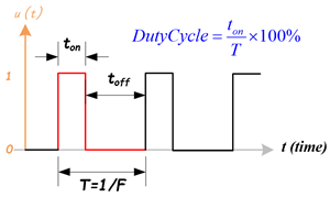
- Duty Cycle
- The duty cycle describes the amount of time the signal is in a high (ON) state as a percentage of the total time it takes to complete one cycle. A lower duty cycle corresponds to lower power, because the power is OFF for most of the time. Duty cycle is expressed in percent, 100% duty cycle would be fully ON as same as setting the signal to Vcc (high); 0% duty cycle would be the same as grounding the signal.
- Frequency
- The frequency determines how fast the PWM completes a cycle, ie. 100Hz would be 100 cycles per second. In another words, it shows how fast the PWM switches between high and low states. In the digital system, PWM is the method to produce variable voltage using digital means. Typically, digital system only has two output voltages, the high (5V, 3.3V … etc.) or low (0V).
Types of PWM
There are a couple of types of PWM, and it can be classified in different ways. There are two kinds of PWM signals: Symmetric and Asymmetric.
Symmetric PWM
- The pulses of a symmetric PWM signal are always symmetric with respect to the center of each PWM period.
- Symmetric PWM are often used for three-phase AC induction and brushless DC motors, due to the lower harmonic distortion that is generated on phase currents in comparsion to asymmetric PWM methods.
Asymmetric PWM
- The pulses of an asymmetric PWM signal always have the same side aligned with one end of each PWM period.
- Asymmetric PWM can be used for stepper motors and other variable-reluctance motors.
Classifying PWM Signal by Signal-Alignment
The PWM signal can be classified by signal-alignment in four different types:
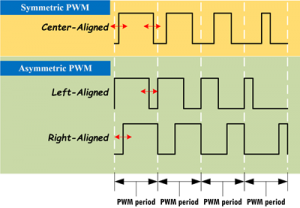
- Center-aligned PWM:
- Symmetric PWM
- Center-aligned PWMs are most often used in AC motor control to maintain phase alignment
- Left-aligned PWM
- Asymmetric PWM
- Left-aligned PWMs are used for most general-purpose PWM uses
- Right-aligned PWM
- Asymmetric PWM
- Right-aligned PWMs are typically only used in special cases that require alignment opposite of left-aligned PWMs
- Dual-edge PWM
- Dual-edged PWMs are optimized for power conversion where phase alignment must be adjusted
PWM Modules in the TM4C123GH6PM MCU System
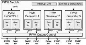
The TM4C123GH6PM MCU contains two PWM modules, PWM0 and PWM1. Each module has four PWM generator blocks and a control block, and each generator block can create two PWM output signals, therefore a total of 16 PWM output signals can be generated by these two modules. The control block determines the polarity of the PWM signals, and it also determines which signals are passed through to the output pins.
Following are the basic facts about the PWM features of TI Tiva LaunchPad:
- There are two PWM modules, PWM0 and PWM1.
- Each PWM module has four Generators.
- Each Generator has a Counter (Timer).
- Each Generator has two Compare registers CMPA and CMPB.
- Each Generator has two output pins, which means there are a total of 8 PWM pins per module.
- The Counter of the Generator can be programmed to count-up or count-up/down.
- As the Counter counts , it may change the output pin when the counter value matches the:
- Compare register(s),
- reaches zero, or is
- reloaded.
The options for output pin change are:
- toggle,
- driven LOW, or
- driven HIGH.
The PWM Generator Block
In the TM4C123GH6PM MCU system, each PWM generator block is composed of two components:
- One 16-bit Counter or Timer and
- Two PWM Comparators, cmpA and cmpB.
The counter provides a timing base for two comparators, and it is mainly used to perform count-down or count-up/down functions to provide a comparison source for two comparators.
The PWM Counter (Timer)
The 16-bit counter or timer in each PWM generator runs in one of two modes, Count-Down mode or Count-Up/Down mode:
- In Count-Down mode, the timer counts from the LOAD value to 0, and then it goes back to the LOAD value and continues to perform the counting down.
- In Count-Up/Down mode, the timer counts from 0 up to the LOAD value and then counts down back to 0, back up to the LOAD value, and so on. Generally, Count-Down mode is used for generating left-aligned or right-aligned PWM signals, and the Count-Up/Down mode is used to generate center-aligned PWM signals.
The timers output three signals that can be used in the PWM generation process:
- The direction signal.
- This signal is always LOW in Count-Down mode, but alternates between LOW and HIGH in Count-Up/Down mode.
- A single-clock-cycle-width High pulse when the counter gets zero.
- A single-clock-cycle-width High pulse when the counter is equal to the LOAD value.
The PWM Comparators
Each PWM generator has two comparators that monitor the value of the counter and output a single-clock-cycle-width HIGH when either comparator’s value is equal to the counting value in the counter. These outputs are labeled cmpA and cmpB. In the Count-Up/Down mode, these comparators match both when counting up and when counting down and thus are qualified by the counter direction signal. If either comparator match-value is greater than the counter load value, that comparator never outputs a High pulse.
 (a) PWM Count-Down Mode
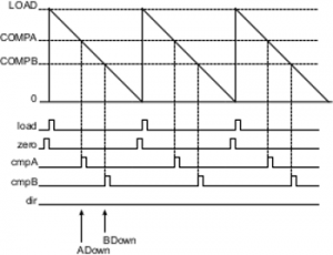
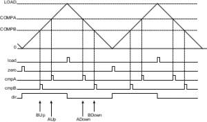 (b) PWM Count-Up/Down Mode
Figure 14.2(a) shows the behavior of the counter and the relationship of these pulses when the counter is in Count-Down mode.
Figure 14.2(b) shows the behavior of the counter and the relationship of these pulses when the counter is in Count-Up/Down mode.
The PWM Output Signals Generator
Each PWM generator uses the load, zero, cmpA, and cmpB pulses and the dir signal to generate two internal PWM signals, pwmA and pwmB, as shown in Figure 14.3.
In Count-Down mode, four events can affect these signals: zero, load, match A down, and match B down. In Count-Up/Down mode, six events can affect these signals: zero, load, match A down, match A up, match B down, and match B up. The match A or match B events are ignored when they coincide with the zero or load events. If the match A and match B events coincide, the first signal, pwmA, is generated based only on the match A event, and the second signal, pwmB, is generated based only on the match B event.
Each event can affect each output PWM signal by programming to make the output to be:
- Left alone (ignoring the event)
- Toggled
- Driven Low or High
These actions can be used to generate a pair of PWM signals of various positions and duty cycles, which do or do not overlap. Figure 14.3 shows the use of Count-Up/Down mode to generate a pair of center-aligned, overlapped PWM signals that have different duty cycles. The pwmA and pwmB signals shown in this figure are before they have passed through the dead-band generator.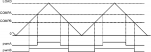
In Figure 14.3, the first PWM generator is set to output High on match A up (COMPA), output Low on match A down (COMPA), and ignore the other four events. The second PWM generator is set to output High on match B up (COMPB ), output Low on match B down (COMPB), and ignore the other four events. Changing the value of comparator A (COMPA) changes the duty cycle of the pwmA signal, and changing the value of comparator B (COMPB) changes the duty cycle of the pwmB signal.
In addition to normal PWM outputs, these two PWM output signals can be combined together to form a so-called Dead-Band output to drive a half-H bridge circuit for some motors.
The Dead-Band Generator
The pwmA and pwmB signals generated by each PWM generator can be passed to the dead-band generator. If the dead-band generator is disabled, these PWM signals can be passed through to the pwmA’ and pwmB’ signals without any modification. If the dead-band generator is enabled, the pwmB signal is ignored and only the pwmA signal is used to generate two PWM signals, pwmA’ and pwmB’.
The first output PWM signal, pwmA’, is the pwmA signal with the rising edge delayed by a programmable amount. The second output PWM signal, pwmB’, is just the inversion of the pwmA signal with a programmable delay added between the falling edge of the pwmA signal and the rising edge of the pwmB’ signal, as shown in Figure 14.4.
The resulting signals are therefore suitable for driving a half-H bridge, with the dead-band delays preventing shoot-through current from damaging the power electronics. These resulting pwmA’ and pwmB’ signals will be transmitted to the output control block.
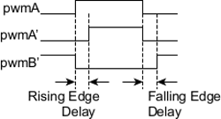
Figure 14.4: PWM Dead-Band Generator.
Recent Comments