
ABSTRACT
The main aim of the experiment is to understand setting up PWM using the sysfs calls which is purely hardware PWM, set PWM using pigpio aand schedule this with real time priority and the observe how the output of the PWM changes . To achieve the set objectives pigpio is installed with pigpiod daemon to use it in the code. “sched.h” file is used for scheduling PWM. The conclusion from this experiment
depends on the CPU load and to achieve higher CPU load empty threads are created and run. Finally the problems faced during the experiment and methods to circumvent those are also discussed.
INTRODUCTION
PWM is a important hardware functionality and many Microcontrollers and Processors provide this functionality directly in the hardware. BCM2711 broadcom processor is the brain of Raspberry pi 4 board and has two PWM modules, PWM0 and PWM1. Each PWM module has two outputs the block diagram of the single PWM is shown in the figure 1.
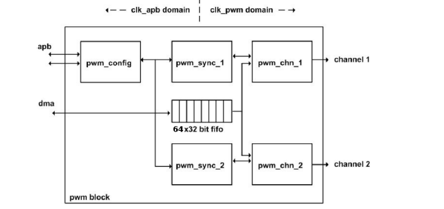
Figure 1: Block Diagram of PWM Module
The hardware PWM can be configured at GPIO 12, 13, 18 or 19. The PWM1 module is mapped to the GPIO12 and GPIO13 whereas PWM module0 is mapped to GPIO18 and GPIO19. This is shown in the snippet from the Broadcom Datasheet in figure

Figure 2: GPIO18,19,12 and 13 with there Alternate functions
II PWM USING SYSFS :
Just like in the first assignment Raspberry pi os provides sysfs method to directly write the settings to the hardware. This is done by following the method given here.
1. Edit the config.txt in the location /boot/firmware/config.txt. In the older versions its inside /boot/config.txt in new version the file is there with suggestion to go to the firmware folder This is important location and contains config.txt and also cmdline.txt. The content inside this location is shown in the figure
3 Once in this location open the config.txt and append the following lines to the end, inserting it anywhere else is useless.
1 dtoverlay=pwm-2chan
2. Once the file is edited and saved reboot. This will create a new sysfs for PWM folder and is shown in the figure 4. the new
location is /sys/class/pwm/pwmchip0
Now using the following two commands will enable the two channels for configuration
1 . $echo 0 > export
2. $echo 1 > export
To use PWM on GPIO18 which is mapped to PWM 0 three steps need to be followed
1. Set the period: period
2. Set the duty cycle: duty cycle
3. Enable the GPIO: enable
The implementation of these steps are shown in the figure 5
This immediately configures PWM and pulses can be seen in the scope with set frequency and duty cycle.
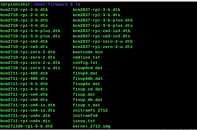
Figure 3: Location of config.txt
Figure 4: New sysfs class with pwm folder is created

Figure 5: Enabling PWM of known Frequency and Duty cycle using sysfs
III PWM USING PIGPIO .
The pigpio library provides a versatile way to control GPIO pins on the Raspberry Pi, allowing for both software and hardware PWM generation. Here’s a brief overview of how to configure PWM using pigpio:
1. Initialization: Begin by calling gpioInitialise(), which sets up the library and must be done before any other pigpio functions. Call gpioTerminate() at the end to clean up.
2. Software PWM: Use gpioSetPWMfrequency(GPIO, frequency) to set the PWM frequency on a specific GPIO pin. Then, call gpioPWM(GPIO, dutycycle) to set the duty cycle, where the dutycycle ranges from 0 (off) to 255 (full power).
3.Hardware PWM: On specific GPIO pins (like GPIO 18 or GPIO 19), pigpio allows hardware PWM, which supports higher resolution and frequencies. Use gpioHardwarePWM(GPIO, frequency, dutycycle) where the dutycycle ranges from 0 to 1,000,000 (0% to 100%).
The pigs utility is a command-line tool that comes with the pigpio library, allowing quick and direct control of GPIO pins without writing a full program. It is useful for testing the setup and functionality of the pigpio library immediately after installation. This test method is shown in the figure 6.The daemon pigpiod needs to be run before the actual command. to install use following commands,
1. $sudo apt-get update
2. $sudo apt-get install pigpio
The pigs method can even be used to set the priority as in the following commands
1 . $sudo chrt -f 99 pigs pwm 17 200 # Start pigs with SCHED_FIFO and priority 99
2.$sudo chrt –deadline 500000:500000:1000000 pigs pwm 17 200
• In the first command:
-f specifies the SCHED FIFO policy. 99 is the real-time priority (range: 1 to 99, where 99 is the highest). pigs p 19 200 is the PWM command for GPIO 19 with a duty cycle of 200. The process will now run with the SCHED FIFO policy, meaning it will not be preempted unless a higher-priority task starts.
• In the second command:
–deadline runtime:deadline:period defines the timing parameters in nanoseconds:
runtime: Maximum time the task is allowed to run (e.g., 500000 ns = 500 µs).
deadline: Time by which the task must complete (e.g., 500000 ns). period: How often the task will run (e.g., 1000000 ns = 1
ms). This sets a deadline for the pigs command, where it has to complete the task within the specified period and runtime, which can help in achieving precise PWM control.
The shortfall of the pigs method is that PWM frequency is fixed at 1 KHz and cannot be changed. Hence different method is used for finer control.

Figure 6: Usage of Pigs command for quick verification
IV FINAL I MPLEMENTATION AND TESTING :
4.1Libraries used:
#include <pigpio.h>
#include <stdio.h>
#include <pthread.h> // for threading
#include <unistd.h>
#include <sched.h> // For real-time scheduling
4.2 Macros used:
Macros used:
#define GPIO_PIN_17 17
#define GPIO_PIN_27 27
#define FREQUENCY_17 1000000
// Frequency for GPIO 17
#define FREQUENCY_27 1000000 // Frequency for GPIO 27 (higher frequency to
simulate higher priority)
#define MAX_DUTY_CYCLE 255 // Maximum duty cycle (0-255)
#define STEP 13 // 5% of 255 is approximately 51
4.3 Thread Functions:
// Thread function for GPIO 27
void *pwm_gpio_27(void *arg)
{
// Set real-time scheduling parameters
struct sched_param param;
param.sched_priority = 99; // Set priority (must be between 1 and 99)
if (sched_setscheduler(0, SCHED_FIFO, ¶m) != 0)
{
perror(“sched_setscheduler”);
return NULL;
}
gpioSetMode(GPIO_PIN_27, PI_OUTPUT);
gpioSetPWMfrequency(GPIO_PIN_27, FREQUENCY_27);
int duty_cycle = 0;
int direction = 1; // 1 for increasing, -1 for decreasing
while (1) {
gpioPWM(GPIO_PIN_27, duty_cycle);
printf(“PWM on GPIO %d set to duty cycle %d\n”, GPIO_PIN_27, duty_cycle);
// Update duty cycle
duty_cycle += STEP * direction;
if (duty_cycle >= MAX_DUTY_CYCLE || duty_cycle <= 0)
{
direction *= -1; // Change direction
duty_cycle = (duty_cycle > MAX_DUTY_CYCLE) ? MAX_DUTY_CYCLE : duty_cycle;
// Sleep for 1 second
sleep(1);
}
return NULL;
}
// Thread function for GPIO 17
void *pwm_gpio_17(void *arg) {
gpioSetMode(GPIO_PIN_17, PI_OUTPUT);
gpioSetPWMfrequency(GPIO_PIN_17, FREQUENCY_17);
int duty_cycle = 0;
int direction = 1; // 1 for increasing, -1 for decreasing
while (1) {
gpioPWM(GPIO_PIN_17, duty_cycle);
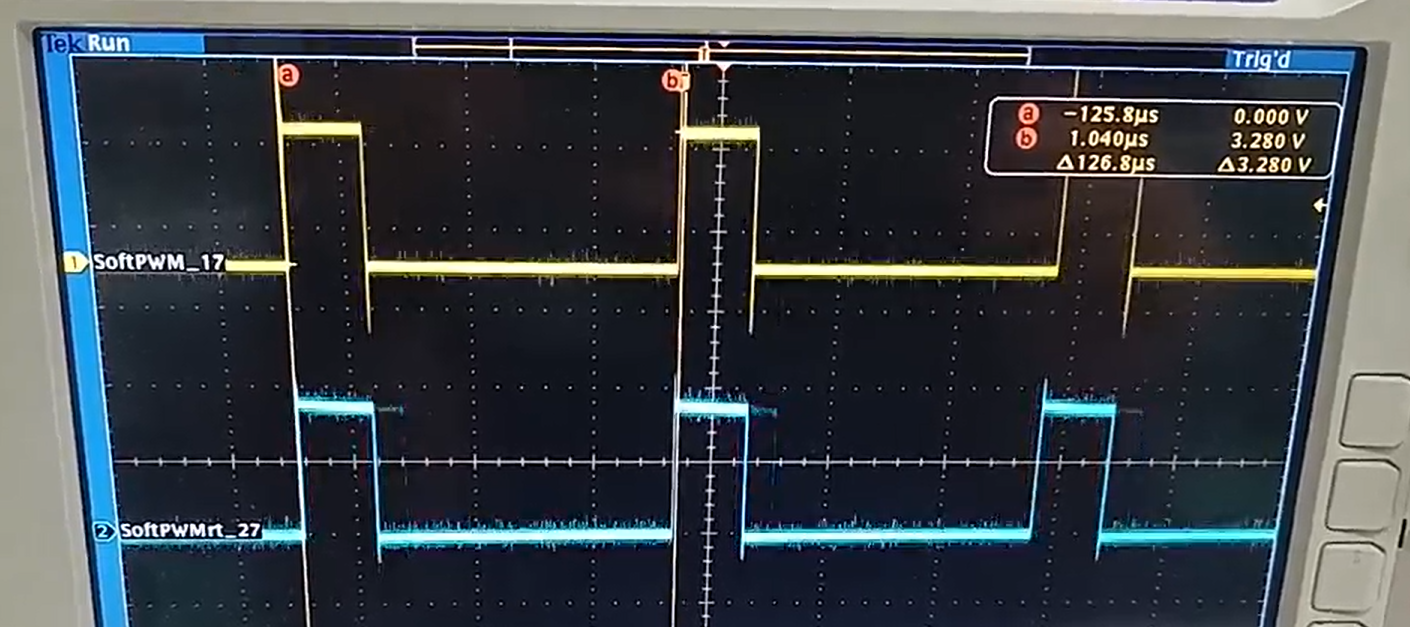
Figure 7: SoftPWM on GPIO 27 with Real time priority is in blue and SoftPwm on GPIO 17 with normal priority in Yellow
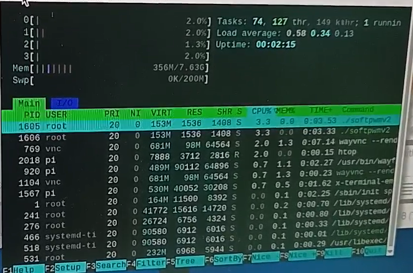
Figure 8: Very less load without empty threads
printf(“PWM on GPIO %d set to duty cycle %d\n”, GPIO_PIN_17, duty_cycle);
// Update duty cycle
duty_cycle += STEP * direction;
if (duty_cycle >= MAX_DUTY_CYCLE || duty_cycle <= 0)
{
direction *= -1; // Change direction
duty_cycle = (duty_cycle > MAX_DUTY_CYCLE) ? MAX_DUTY_CYCLE : duty_cycle;
// Sleep for 1 second
sleep(1);
}
return NULL; }
Here GPIO 27 is set with highest priority (99) and GPIO 17 is normal priority. Here PWM is not enabled and processor load is very less, the two PWM changes at the same time. This is shown in the figure ……… During this event the processor load is shown in the figure ..
To increase the processor load following code with 200 empty threads is run this is given in the next code section.
4.4 Run 200 empty threads:
#include <stdio.h>
#include <stdlib.h>
#include <pthread.h>
#define NUM_THREADS 200 // Number of threads (adjust based on how much CPU load you
want)
void *load_cpu(void *arg) {
// Infinite loop to simulate CPU load
while (1) {
// Perform a simple task to consume CPU (like an empty loop)
// You can add some dummy computations if needed.
}
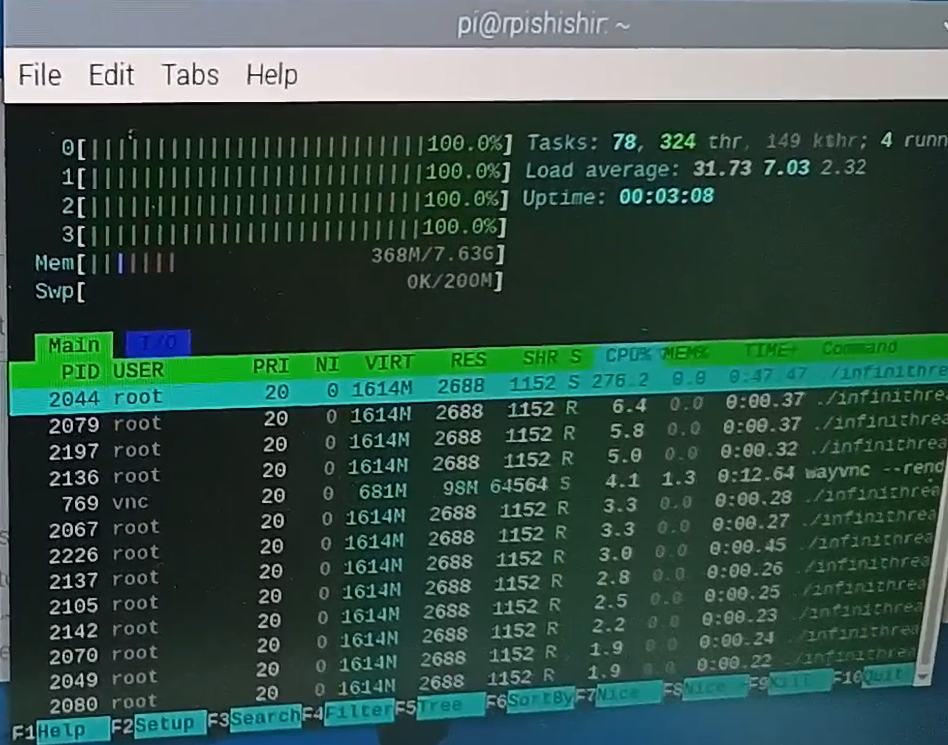
Figure 9: Processor loaded to 100 percent
return NULL; }
int main() {
pthread_t threads[NUM_THREADS]; // Array of thread identifiers
int i;
int ret;
// Create multiple threads to load the CPU
for (i = 0; i < NUM_THREADS; i++) {
ret = pthread_create(&threads[i], NULL, load_cpu, NULL);
if (ret) {
printf(“Error creating thread %d: %d\n”, i, ret);
return 1;
}
printf(“Thread %d created successfully\n”, i);
}
// Join threads (optional: in this case, they run forever, so we don’t join them)
for (i = 0; i < NUM_THREADS; i++) {
pthread_join(threads[i], NULL);
// Wait for each thread to finish (it won’t in this case)
}
return 0; }
This results in all the cores of the processor being loaded to 100% this is shown in figure …
Because of the processor load now the PWM duty cycles on the processes having different priority begins to differ, this is shown in the figure ….
This is at the maximum Software frequency which can be achieved by using pigpio library and is equal to 8 KHz.
4.5 Enabling Hardware PWM and changing its duty cycle using pigpio library:
#include <pigpio.h>
#include <stdio.h>
#include <pthread.h>
#include <unistd.h>
#include <sched.h> // For real-time scheduling
#define GPIO_PIN_17 17
#define GPIO_PIN_27 27
#define GPIO_PIN_18 18 // GPIO 18 for hardware PWM
#define FREQUENCY 50000
// Frequency for all GPIOs (5 kHz)
#define MAX_DUTY_CYCLE 255
// Maximum duty cycle for software PWM (0-255)
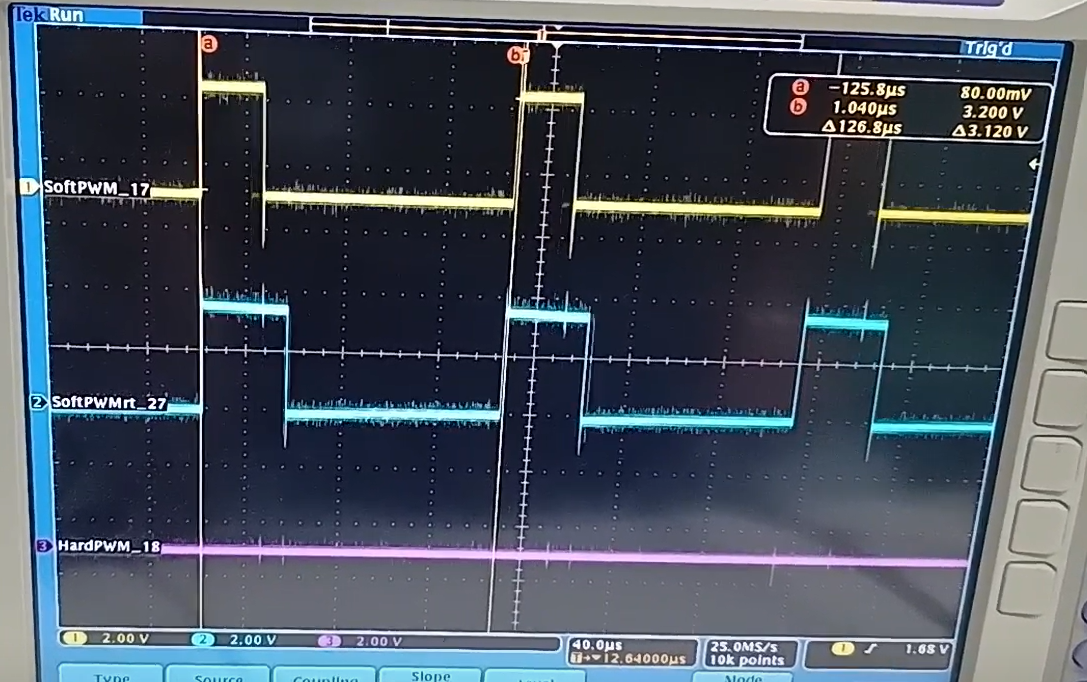
Figure 10: Blue starts to lead and is updated before yellow upon higher processor loads
#define MAX_HARDWARE_DUTY 1000000 // Maximum duty cycle for hardware PWM
(0-1,000,000)
#define STEP 51
// 20% of 255 is approximately 51 for software PWM
#define HARDWARE_STEP 200000
// 20% of 1,000,000 for hardware PWM
// Shared duty cycle and control variables int shared_duty_cycle = 0;
int shared_direction = 1; // 1 for increasing, -1 for decreasing
// Separate duty cycle variables int duty_cycle_17 = 0;
int duty_cycle_27 = 0;
int duty_cycle_18 = 0;
// Thread function for GPIO 27 (Software PWM with real-time priority)
void *pwm_gpio_27(void *arg)
{
// Set real-time scheduling parameters
struct sched_param param;
param.sched_priority = 98; // Set priority (must be between 1 and 99)
if (sched_setscheduler(0, SCHED_FIFO, ¶m) != 0)
{
perror(“sched_setscheduler”);
return NULL;
}
gpioSetMode(GPIO_PIN_27, PI_OUTPUT);
gpioSetPWMfrequency(GPIO_PIN_27, FREQUENCY);
while (1) {
gpioPWM(GPIO_PIN_27, duty_cycle_27);
// Sleep for a short
time to avoid excessive CPU usage
// usleep(10);
}
return NULL; }
// Thread function for GPIO 17 (Software PWM)
void *pwm_gpio_17(void *arg) {
gpioSetMode(GPIO_PIN_17, PI_OUTPUT);
gpioSetPWMfrequency(GPIO_PIN_17, FREQUENCY);
while (1) {
gpioPWM(GPIO_PIN_17, duty_cycle_17);
// Sleep for a short time to avoid
excessive CPU usage
// usleep(10);
}
return NULL; }
// Thread function for GPIO 18 (Hardware PWM with real-time priority)
void *pwm_gpio_18(void *arg) {
// Set real-time scheduling parameters
struct sched_param param;
param.sched_priority = 99; // Slightly higher priority than GPIO 27
if (sched_setscheduler(0, SCHED_FIFO, ¶m) != 0) {
perror(“
sched_setscheduler”);
return NULL;
}
while (1) {
gpioHardwarePWM(GPIO_PIN_18, FREQUENCY, duty_cycle_18);
// Direct duty cycle
// Sleep for a short time to avoid excessive CPU usage
//usleep(1000);
}
return NULL; }
// Thread function to adjust the shared duty cycle
void *duty_cycle_adjuster(void *arg) {
while (1) {
shared_duty_cycle += STEP * shared_direction;
if (shared_duty_cycle >= MAX_DUTY_CYCLE || shared_duty_cycle <= 0)
{
shared_direction *= -1; // Change direction
shared_duty_cycle = (shared_duty_cycle > MAX_DUTY_CYCLE) ? MAX_DUTY_CYCLE :
shared_duty_cycle;
}
// Update duty cycles for each GPIO
duty_cycle_17 = shared_duty_cycle;
duty_cycle_27 = shared_duty_cycle;
duty_cycle_18 = shared_duty_cycle * (MAX_HARDWARE_DUTY / MAX_DUTY_CYCLE); // Scaled
duty cycle
// Sleep for 1 second
usleep(2000000);
}
return NULL; }
int main() {
if (gpioInitialise() < 0) {
printf(“Failed to initialize
pigpio\n”);
return 1;
}
pthread_t thread_id_17, thread_id_27, thread_id_18, adjuster_thread;
// Create a thread to handle PWM on GPIO 27
if (pthread_create(&thread_id_27, NULL, pwm_gpio_27, NULL) != 0) {
printf(“Failed to create thread for GPIO 27 PWM\n”);
gpioTerminate();
return 1;
}
// Create a thread to handle PWM on GPIO 17
thread_create(&thread_id_17, NULL, pwm_gpio_17, NULL) != 0) {
if (printf(“Failed to create thread for GPIO 17 PWM\n”);
gpioTerminate();
return 1;
}
// Create a thread to handle hardware PWM on GPIO 18
if (pthread_create(&thread_id_18, NULL, pwm_gpio_18, NULL) != 0) {
printf(“Failed to create thread for GPIO 18 hardware PWM\n”);
gpioTerminate();
return 1;
}
// Create a thread to adjust the duty cycle
if (pthread_create(&adjuster_thread, NULL, duty_cycle_adjuster, NULL) != 0) {
printf(“Failed to create duty cycle adjuster thread\n”);
gpioTerminate();
return 1;
}
// Main thread will wait for user input
getchar();
// Clean up and terminate
pthread_cancel(thread_id_17);
// Cancel the PWM thread for GPIO 17
pthread_cancel(thread_id_27); // Cancel the PWM thread for GPIO 27
pthread_cancel(thread_id_18); // Cancel the hardware PWM thread for GPIO 18
pthread_cancel(adjuster_thread); // Cancel the duty cycle adjuster thread
pthread_join(thread_id_17, NULL); // Wait for the thread to finish
pthread_join(thread_id_27, NULL); // Wait for the thread to finish
pthread_join(thread_id_18, NULL); // Wait for the thread to finish
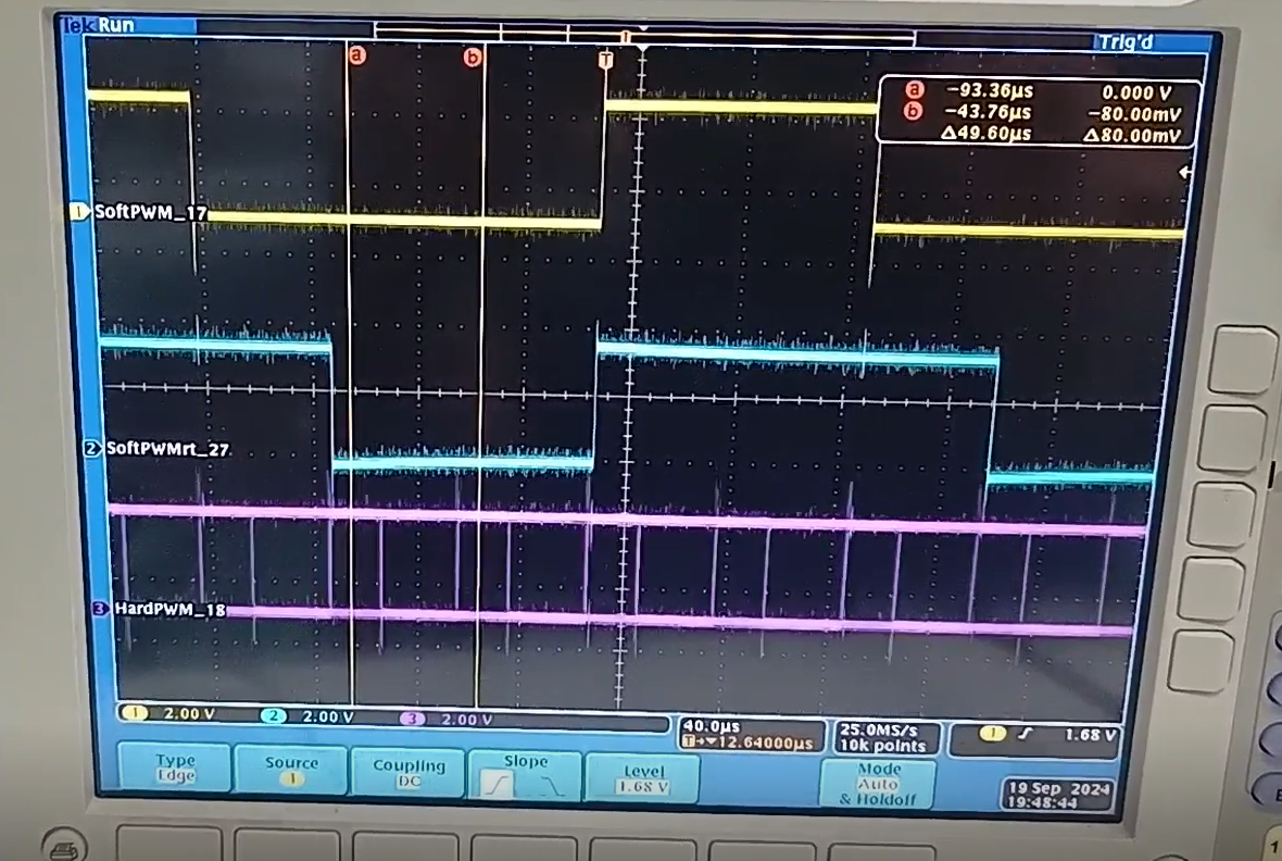
Figure 11: Real time Soft PWM(Blue updates) faster even without creating empty threads because of higher processor load
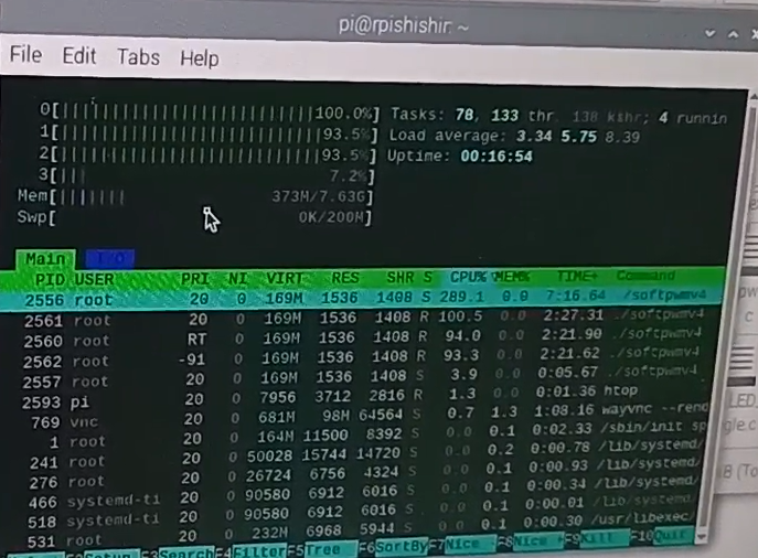
Figure 12: processor loading with enabling PWM at 1 MHz
pthread_join(adjuster_thread, NULL); // Wait for the adjuster thread to finish
gpioTerminate();
return 0;
}
As soon as the Hardware PWM is enabled even without using empty thread processor is loaded but the load varies with time and the effect is seen on the updation of duty cycles for both highest priority process and lower priority process. The effect of priority is more prominent as seen in figure11 .
Even in this case processor is fully loaded. This can be seen in the figure 12 .
V KEYPOINTS :
• The c file needs to be compiled like shown in the script below:
1 $ gcc -o softpwm4 softpwmv4.c -lpigpio -lrt -lpthread
lpigpio: Link using pigio library
-lrt: link using real time library
-lpthread: link using pthread library.
Missing This will cause errors
• Stop the process and kill the Daemon before compiling and running again. This is utmost importance
1 $ sudo pkill -9 softpwmv4
VI CONCLUSION :
1. The Software PWM cannot run at more than 8KHz.
2. Assignment of higher priority/ real time priority improves the performance.
3. CPU is loaded when running Hardware PWM with pigpio library even withod loading with empty threads.
Recent Comments