
| INTRODUCTION | GPIO&INIT | SAMPLE | TASKS |
In this article we are going to deal with GPIO PORTF interrupt that will toggle the on board blue led on rising edge whenever a user switch is pressed. Since the GPIO related initialization has already been discussed in our GPIO section. Here we will look at the initialization rituals for GPIO interrupts only.
As we already know that a micro controller has a built in capability to perform several tasks without waiting for completion of ongoing task. Generally there are two methods by which a peripheral device can receive a service from micro controller, they are:
- Polling
- Interrupts
In polling method a micro controller continuously monitors the status of a device or a particular condition and waits until the required status or condition is met and then it performs the service, after performing this task it executes the next task. For example, just take a look at our section of UART code you can see that we are continuously monitoring the bit 5 of UART0_FR_R register to ensure that any previous transmission has been completed.
    while((UART0_FR_R & 0x00000010) != 0) {
        ;
    }
    UART0_DR_R = data;
If yes, then transmit the next incoming data, while in interrupt the same thing is serviced by a microcontroller without continuously monitoring the status of a device though it serves when it gets notified by the device by receiving an interrupt signal.
Interrupt service routine (ISR)
For every interrupt there must be a program associated with it. When an interrupt occurs this program is executed to perform certain service for the interrupt. This program is commonly referred to as an interrupt service routine (ISR) or interrupt handler. When an interrupt occurs, the CPU runs the interrupt service routine. Now the question is, how the ISR gets executed? As shown in the Table 7.1, in the ARM CPU there are pins that are associated with hardware interrupts. They are input signals into the CPU. When the signals are triggered, CPU pushes the PC register onto the stack and loads the PC register with the address of the interrupt service routine. This causes the ISR to get executed.
Interrupt Vector Table
Since there is a program (ISR) associated with every interrupt and this program resides in memory (RAM or ROM), there must be a look-up table to hold the addresses of these ISRs. This look-up table is called interrupt vector table. In the ARM, the lowest 1024 bytes (256 * 4 = 1024) of memory space are set aside for the interrupt vector table and must not be used for any other function. Of the 256 interrupts, some are used for software interrupts and some are for hardware IRQ interrupts.
Nested Vectored Interrupt Controller (NVIC)
It is a control unit for a cortex-M4 MCU, It provides the group of programmable registers where all the exceptions and interrupts, including maskable and non-maskable interrupts are handled and preprocessed in a specific sequences.
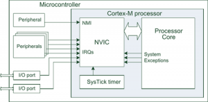
- Interrupts on the Cortex-M are controlled by the Nested Vectored Interrupt Controller (NVIC).
- Each exception has an associated 32-bit vector that points to the memory location where the ISR that handles the exception is located.
With CCS IDE, a new project will get a C startup code tm4c123gh6pm_startup_ccs_gcc.c created by the project wizard. For each interrupt, there is a dummy interrupt hander that does not perform any thing and will never return from the handler. The addresses of these interrupt handlers are listed in the interrupt vector table named g_pfnVectors in the file. You need to carefully find the appropriate vector position and replace IntDefaultHandler with the name of your Interrupt handler. The linker will overwrite the interrupt vector table with the new interrupt handler. The interrupt handler is written with a format of a function in C language.
A detailed default vector table can be found at tm4c123gh6pm_startup_ccs_gcc.c file.
Interrupt and Exception assignments in ARM Cortex-M
The NVIC of the ARM Cortex-M has room for the total of 255 interrupts and exceptions. The interrupt numbers are also referred to as INT type (or INT #) in which the type can be from 1 to 255 or 0x01 to 0xFF. The NVIC in ARM Cortex-M assigns the first 15 interrupts for internal use. The memory locations 0 to 3 are used to store the value to be loaded into the stack pointer when the device is coming out of reset. See Table 7.2
| Interrupt # | Interrupt | Memory Location | Priority Level |
|---|---|---|---|
| 0 | Stack Pointer Initial Value | 0x00000000 | |
| 1 | Reset | 0x00000004 | -3 Highest |
| 2 | NMI | 0x00000008 | -2 |
| 3 | Hard Fault | 0x0000000C | -1 |
| 4 | Memory Management Fault | 0x00000010 | Programmable |
| 5 | Bus Fault | 0x00000014 | Programmable |
| 6 | Usage Fault (undefined instructions, divide by zero, unaligned memory access, ….) |
0x00000018 | Programmable |
| 7 | Reserved | 0x0000001C | Programmable |
| 8 | Reserved | 0x00000020 | Programmable |
| 9 | Reserved | 0x00000024 | Programmable |
| 10 | Reserved | 0x00000028 | Programmable |
| 11 | SVCall | 0x0000002C | Programmable |
| 12 | Debug Moniter | 0x00000030 | Programmable |
| 13 | Reserved | 0x00000034 | Programmable |
| 14 | PendSV | 0x00000038 | Programmable |
| 15 | SysTick | 0x0000003C | Programmable |
| 16 | IRQ for peripherals | 0x00000040 | Programmable |
| 17 | IRQ for peripherals | 0x00000044 | Programmable |
| … | … | … | … |
| 255 | IRQ for peripherals | 0x000003FC | Programmable |
IRQ Peripheral interrupts
- An ISR can be launched as a result of an event at the peripheral devices such as timer timeout or analog-to-digital converter (ADC) conversion complete. The largest number of the interrupts in the ARM Cortex-M belong to this category.
- Notice from Table 7.2 that ARM Cortex-M NVIC has set aside the first 15 interrupts (INT 1 to INT 15) for internal use and exceptions and is not available to chip designer. The Reset, NMI, undefined instructions, and so on are part of this group of exceptions. The rest of the interrupts can be used for peripherals.
- Many of the INT 16 to INT 255 are used by the chip manufacturer to be assigned to various peripherals such as timers, ADC, Serial COM, external hardware interrupts, and so on. There is no standard in assigning the INT 16 to INT 255 to the peripherals.
- Each peripheral device has a group of special function registers that must be used to access the device for configuration.
- For a given peripheral interrupt to take effect, the interrupt for that peripheral must be enabled. The special function registers for that device provide the way to enable the interrupts.
Interrupt Priority for ARM Cortex-M
- All exceptions and interrupts in the Cortex-M4 system have certain priority levels, either maskable or unmaskable sources.
- Most maskable interrupts have programmable priority levels, but all Non-Maskable Interrupts (NMIs) have fixed priority levels.
- When an exception or interrupt occurs, the NVIC performs a comparison between the priority level of current exception or interrupt and the priority level of the new coming exception/interrupt. The current running task will be suspended and the control will be transferred to the service routine of the new coming exception/interrupt if the priority level of the new coming exception/interrupt is higher.
- In the ARM Cortex-M4 system, the interrupt priority levels are controlled by the Interrupt Priority Registers, as shown in Table 7.3.
- Each priority register can use 3 bits, 4 bits, or 8 bits to cover all priority levels used in the priority control system.
- A total of 8 priority levels can be used if 3 bits are used in this register, and 16 priority levels can be obtained if 4 bits are used in this register.
- Devices within the Tiva family support up to 154 interrupt sources and 8 priority levels, which means that 3 bits are used in the priority register in the TM4C123GH6PM MCU.
- To activate an interrupt source we need to set its priority and enable that source in the NVIC. This activation is in addition to the arm and enable steps.
- To arm a device means to allow the hardware trigger to interrupt. Conversely, to disarm a device means to shut off or disconnect the hardware trigger from the interrupts
- Table 7.3 lists some of the interrupt sources available on the TM4C family of micro controllers. Interrupt numbers 0 to 15 contain the faults, software interrupt and SysTick; these interrupts will be handled differently from interrupts 16 and up.
| Vector address |
Vector (Exception) Number |
Interrupt # (IRQ) |
Address (Priority Register) |
Interrupt Source | Priority Register (Tivaware Name) |
Priority Bits |
|---|---|---|---|---|---|---|
| 0x00000038 | 14 | -2 | 0xE000.ED20 | PendSV | NVIC_SYS_PRI3_R | 23 – 21 |
| 0x0000003C | 15 | -1 | 0xE000.ED20 | SysTick | NVIC_SYS_PRI3_R | 31 – 29 |
| 0x00000040 | 16 | 0 | 0xE000.E400 | GPIO Port A | NVIC_PRI0_R | 7 – 5 |
| 0x00000044 | 17 | 1 | 0xE000.E400 | GPIO Port B | NVIC_PRI0_R | 15 – 13 |
| 0x00000048 | 18 | 2 | 0xE000.E400 | GPIO Port C | NVIC_PRI0_R | 23 – 21 |
| 0x0000004C | 19 | 3 | 0xE000.E400 | GPIO Port D | NVIC_PRI0_R | 31 – 29 |
| 0x00000050 | 20 | 4 | 0xE000.E404 | GPIO Port E | NVIC_PRI1_R | 7 – 5 |
| 0x00000054 | 21 | 5 | 0xE000.E404 | UART0, Rx Tx | NVIC_PRI1_R | 15 – 13 |
| 0x00000058 | 22 | 6 | 0xE000.E404 | UART1, Rx Tx | NVIC_PRI1_R | 23 – 21 |
| 0x0000005C | 23 | 7 | 0xE000.E404 | SSI0, Rx Tx | NVIC_PRI1_R | 31 – 29 |
| 0x00000060 | 24 | 8 | 0xE000.E408 | I2C0 | NVIC_PRI2_R | 7 – 5 |
| 0x00000064 | 25 | 9 | 0xE000.E408 | PWM Fault | NVIC_PRI2_R | 15 – 13 |
| 0x00000068 | 26 | 10 | 0xE000.E408 | PWM Gen 0 | NVIC_PRI2_R | 23 – 21 |
| 0x0000006C | 27 | 11 | 0xE000.E408 | PWM Gen 1 | NVIC_PRI2_R | 31 – 29 |
| 0x00000070 | 28 | 12 | 0xE000.E40C | PWM0 Gen 2 | NVIC_PRI3_R | 7 – 5 |
| 0x00000074 | 29 | 13 | 0xE000.E40C | Quad Encoder 0 | NVIC_PRI3_R | 15 – 13 |
| 0x00000078 | 30 | 14 | 0xE000.E40C | ADC Seq 0 | NVIC_PRI3_R | 23 – 21 |
| 0x0000007C | 29 | 15 | 0xE000.E40C | ADC Seq 1 | NVIC_PRI3_R | 31 – 29 |
| 0x00000080 | 32 | 16 | 0xE000.E410 | ADC Seq 2 | NVIC_PRI4_R | 7 – 5 |
| 0x00000084 | 33 | 17 | 0xE000.E410 | ADC Seq 3 | NVIC_PRI4_R | 15 – 13 |
| 0x00000088 | 34 | 18 | 0xE000.E400 | Watchdog | NVIC_PRI4_R | 23 – 21 |
| 0x0000008C | 35 | 19 | 0xE000.E410 | Timer 0A | NVIC_PRI4_R | 31 – 29 |
| 0x00000090 | 36 | 20 | 0xE000.E414 | Timer 0B | NVIC_PRI5_R | 7 – 5 |
| 0x00000094 | 37 | 21 | 0xE000.E414 | Timer 1A | NVIC_PRI5_R | 15 – 13 |
| 0x00000098 | 38 | 22 | 0xE000.E414 | Timer 1B | NVIC_PRI5_R | 23 – 21 |
| 0x0000009C | 39 | 23 | 0xE000.E414 | Timer 2A | NVIC_PRI5_R | 31 – 29 |
| 0x000000A0 | 40 | 24 | 0xE000.E418 | Timer 2B | NVIC_PRI6_R | 7 – 5 |
| 0x000000A4 | 41 | 25 | 0xE000.E418 | Comp 0 | NVIC_PRI6_R | 15 – 13 |
| 0x000000A8 | 42 | 26 | 0xE000.E418 | Comp 1 | NVIC_PRI6_R | 23 – 21 |
| 0x000000AC | 43 | 27 | 0xE000.E418 | Comp 2 | NVIC_PRI6_R | 31 – 29 |
| 0x000000B0 | 44 | 28 | 0xE000.E41C | System Control | NVIC_PRI7_R | 7 – 5 |
| 0x000000B4 | 45 | 29 | 0xE000.E41C | Flash Control | NVIC_PRI7_R | 15 – 13 |
| 0x000000B8 | 46 | 30 | 0xE000.E41C | GPIO Port F | NVIC_PRI7_R | 23 – 21 |
| 0x000000BC | 47 | 31 | 0xE000.E41C | GPIO Port G | NVIC_PRI7_R | 31 – 29 |
| 0x000000C0 | 48 | 32 | 0xE000.E420 | GPIO Port H | NVIC_PRI8_R | 7 – 5 |
| 0x000000C4 | 49 | 33 | 0xE000.E420 | UART2, Rx Tx | NVIC_PRI8_R | 15 – 13 |
| 0x000000C8 | 50 | 34 | 0xE000.E420 | SSI1, Rx Tx | NVIC_PRI8_R | 23 – -21 |
| 0x000000CC | 51 | 35 | 0xE000.E420 | Timer 3A | NVIC_PRI8_R | 31 – 29 |
| 0x000000D0 | 52 | 36 | 0xE000.E424 | Timer 3B | NVIC_PRI9_R | 7 – 5 |
| 0x000000D4 | 53 | 37 | 0xE000.E424 | I2C1 | NVIC_PRI9_R | 15 – 13 |
| 0x000000D8 | 54 | 38 | 0xE000.E424 | Quad Encoder 1 | NVIC_PRI9_R | 23 – 21 |
| 0x000000DC | 55 | 39 | 0xE000.E424 | CAN0 | NVIC_PRI9_R | 31 – 29 |
| 0x000000E0 | 56 | 40 | 0xE000.E428 | CAN1 | NVIC_PRI10_R | 7 – 5 |
| 0x000000E4 | 57 | 41 | 0xE000.E428 | CAN2 | NVIC_PRI10_R | 15 – 13 |
| 0x000000E8 | 58 | 42 | 0xE000.E428 | Ethernet | NVIC_PRI10_R | 23 – 21 |
| 0x000000EC | 59 | 43 | 0xE000.E428 | Hibernate | NVIC_PRI10_R | 31 – 29 |
| 0x000000F0 | 60 | 44 | 0xE000.E42C | USB0 | NVIC_PRI11_R | 7 – 5 |
| 0x000000F4 | 61 | 45 | 0xE000.E42C | PWM Gen 3 | NVIC_PRI11_R | 15 – 13 |
| 0x000000F8 | 62 | 46 | 0xE000.E42C | uDMA Soft Tfr | NVIC_PRI11_R | 23 – 21 |
| 0x000000FC | 63 | 47 | 0xE000.E42C | uDMA Error | NVIC_PRI11_R | 31 – 29 |
The following five conditions must be true for an interrupt to be generated:
- Device arm
- Each potential interrupt trigger has a separate arm bit that the software can activate or deactivate. The software will set the arm bits for those devices from which it wishes to accept interrupts, and will deactivate the arm bits within those devices from which interrupts are not to be allowed. In other words it uses the arm bits to individually select which devices will and which devices will not request interrupts.
- NVIC enable
- For most devices there is a enable bit in the NVIC that must be set (periodic SysTick interrupts are an exception, having no NVIC enable).
- Global enable
- Bit 0 of the special register PRIMASK is the interrupt mask bit, I. If this bit is 1 most interrupts and exceptions are not allowed, which we will define as disabled. If the bit is 0, then interrupts are allowed, which we will define as enabled.
- Interrupt priority level must be higher than current level executing
- The BASEPRI register prevents interrupts with lower priority interrupts, but allows higher priority interrupts. For example if the software sets the BASEPRI to 3, then requests with level 0, 1, and 2 can interrupt, while requests at levels 3 and higher will be postponed. The software can also specify the priority level of each interrupt request. If BASEPRI is zero, then the priority feature is disabled and all interrupts are allowed.
- Hardware event trigger.
- Hardware triggers are bits in the GPIO_PORTx_RIS_R register that are set on rising or falling edges of digital input pins.
For an interrupt to occur, these five conditions must be simultaneously true but can occur in any order.
Recent Comments