
Device Tree and Boot Flow
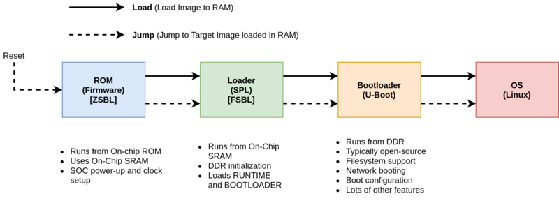
Embedded Linux Boot Flow
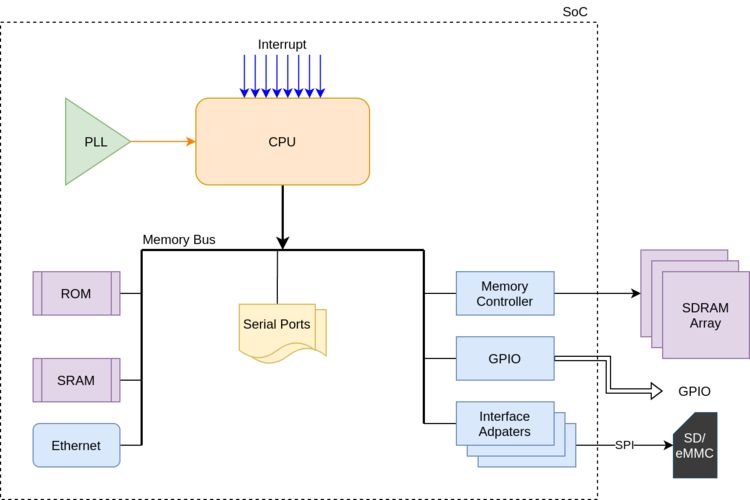
SoC Architecture
Bootloader (U-Boot)
A boot-loader is a small program which will load the kernel image into RAM and boots up the kernel image. This is also called bootstrap as it brings(pulls) up system by loading an operating system. Boot-loader starts before any other software starts and initializes the processor and makes CPU ready to execute a program like an operating system. Most processors have a default address from which the first bytes of code are fetched upon power is applied or board is reset. Hardware designers use this information to store the boot-loader code at that address in ROM or flash. Since it should initialize the cpu and should run a program which is located at architecture specific address boot-loaders are highly processor specific and board specific. Every embedded board comes with a bootstrap to download the kernel image or standalone application into the board and start executing the kernel image or application. Boot-loader will be executed when power is applied to a processor board. Basically it will have some minimal features to load the image and boot it up.
U-Boot boots an operating system by reading the kernel and any other required data (e.g. device tree or ramdisk image) into memory, and then executing the kernel with the appropriate arguments.
Correlation of x86 PC World & Embedded World
| Stage | x86 (PC) | Embedded (BeagleBone) |
|---|---|---|
| ZSBL (Firmware) | BIOS/UEFI | Firmware Present in On-Chip ROM |
| FSBL (SPL Loader) | GRUB Stage 1<br />/boot/efi/EFI/ubuntu/shimx64.efi |
MLO (Mmc LOader) |
| Bootloader | GRUB Stage 2<br />/boot/grub |
u-boot.bin |
Zeroth Stage BootLoader (Firmware)
The AM335x contains a section of Read-Only Memory (ROM) that implements the first stage bootloader. The ROM Bootloader code is the first piece of code that is executed by the processor when it is released from reset. The ROM is a hard coded piece of software and cannot be changed for a given device but may change between revisions of the processor. The ROM bootloader has the following responsibilities:
- Initial configuration of the device and initialization of boot peripherals
- Memory section setup (stack, heap, etc.)
- Configuration of Watchdog Timer 1 (set to three minutes)
- Configuration of PLL and System Clocks
- Load and begin execution of the next stage bootloader
- Check boot peripherals for next stage bootloader (SPL/MLO)
- Load bootloader from peripheral into the internal RAM of the AM335x and begin execution of the code
Memory Booting: If the device is XIP (eXecute In Place), the directly jumps to target address, otherwise copies image into target RAM and jumps to target address. Example of XIP device is NOR Flash Memory which can be memory mapped (unlike eMMC).
MMC/SD Card Booting: Initialise MMC/SD driver. If card is present and readable, checks for card access modes like Raw Mode, FAT Mode, MBR, FAT16/32 Boot Sector.
In Raw Mode, the booting image can be located at one of the four consecutive locations in the main area:
offset 0x0 / 0x20000 (128 KB) / 0x40000 (256 KB) / 0x60000 (384 KB). For this reason, a booting image
shall not exceed 128KB in size.
This is why we copy MLO to SD-Card at offset of 0x20000 using command
sudo dd if=./u-boot/MLO of=${DISK} count=1 seek=1 bs=128k.
In FAT mode, The image used by the booting procedure is taken from a specific booting file named “MLO”. This file has to be located in the root directory on an active primary partition of type FAT16 or FAT32. Firmware loads MLO/SPL image to 0x402F0400 i.e. internal SRAM of AM335xx SoC
First Stage BootLoader (SPL: Secondary Program Loader)
The SPL must operate entirely within the internal memory of the AM335x processor since only the boot peripherals have been initialized by the ROM bootloader.
To boot Linux, one of the most common methods is to use U-Boot (Universal Boot Loader) to perform all of the steps necessary to load and boot the Linux kernel. Feature rich U-Boot environment requires more memory than is available in the AM335x internal memory. Therefore, U-Boot is split into a first-stage and second-stage bootloader. The first stage of U-Boot is small and can be used as the SPL for the AM33xx Linux boot process. This split is done automatically during the build process for U-Boot, but the pieces are loaded into separate parts of the boot image.
The main function of the stripped-down SPL version of U-Boot is to perform hardware initialization of the DDR3 memory within the AM33xx, load the larger, fully featured version of U-Boot into DDR memory, and begin execution of that code.
e.g. MLO,
In U-Boot Config for BeagleBone Black Wireless the U-Boot address i.e. address of u-boot.bin in SD-Card is defined as sector 0x300 i.e. 0xC0000.
This is why we copy u-boot.bin at offset of 0xC0000 (384k) using commandsudo dd if=./u-boot/u-boot.img of=${DISK} count=2 seek=1 bs=384k
Beaglebone Black Boot Flow with U-Boot
The main function of the U-Boot bootloader is to load and begin execution of the Linux kernel. To do this, it will typically look for a uImage or zImage file. The Kernel Image file can be found in non-volatile memory attached to the processor, such as an eMMC or a microSD card, or over a network interface via a protocol like TFTP.
The U-Boot environment can be configured by setting environment variables. These environment variables can be 1) configured during the build of U-Boot; 2) set and saved during an interactive U-Boot session; or 3) set or overridden from a file called uEnv.txt which is stored in the /boot directory of the filesystem.
The boot script checks for the existence of a file called uEnv.txt. If the file is found, the file is loaded into the memory. Then, it is imported to the environment ready to be read or executed. The uEnv.txt file is a method for users to insert scripts into the environment.
The complete Flattened boot scipt is available here. Upon boot environment variable bootcmd is executed.
Device Tree :: Concepts
Generally peripherals are connected to processor via a bus like USB, PCI, SATA, HDMI. All modern PC buses support enumeration. i.e. the main processor can ask “what devices are connected to this bus?” and the devices reply with some information about their type, manufacturer, model and configuration in a standardized format. With that information, the operating system can report the list of available devices and decide which device driver to use for each of them.
So Why do we need Device Tree?
Device Tree used to pass information about device which cannot be discovery so that OS can decide driver to use and configure it. E.g. UART/SPI/I2C, DMA Controller, No. of CPUs, Cache Organization, clock Frequency etc. Also many embedded system uses buses that doesn’t support enumeration e.g. AXI, AHB. Without enumeration, the operating system has to be told what devices are present and how to access them. The ‘Device Tree’ is a standard format to represent this information.
History
Before the Device Tree, the Linux kernel contained the all of the knowledge regarding the hardware of each supported platform. This data, like memory locations, interrupts, on chip peripherals and lots of, many, alternative things was compiled into the kernel. This approach worked fairly well once there have been simply a number of platforms being supported.
Due to the fact that a description of every hardware platform was built into the kernel source, the boot loader could tell the kernel which platform it was running on by passing in a value (known as the machine type integer) at start up. The kernel would then internally look up the appropriate platform parameters and then use them to figure out how to utilize the hardware available to it.
There are problems with this hard coded approach. The first problem is that recent times have seen an ever proliferating number of small microcontroller boards each with their own set of hardware. Maintainers were having a hard time keeping up. Linus declared that henceforth no longer would each and every new device be supported in the mainline kernel and that a new solution must be found.
The choice of forking the Linux kernel code and implementing non-mainline configurations for each new micro-controller was really not a serious long term option and so the Device Tree concept was developed. The Device Tree enables micro-controllers to use the same mainline kernel code along with a separate, board specific, hardware configuration. Mainline Linux kernel version 3.7 and higher all support the Device Tree.
ePAPR (Power.org Standard for Embedded Power Architecture Platform Requirements)
The ePAPR specifies a concept called a device tree to describe system hardware. A boot program loads a device tree into a client program’s memory and passes a pointer to the device tree to the client.
vDevice Tree : Embedded s PC (x86)
The main reason PC buses support discovery is that they’re designed to allow a modular architecture where devices can be added and removed, e.g. adding an extension card into a PC or connecting a cable on an external port. Embedded systems typically have a fixed set of devices (excluding USB peripherals), and an operating system that’s pre-loaded by the manufacturer and doesn’t get replaced, so enumeration is not necessary.
So How Non-Enumerable Devices information is Passes to OS in PC?
ACPI (Advanced Configuration and Power Interface) started as an interface between firmware (formerly BIOS) and OS for things like power management, but also things like platform device probing. In ACPI there is a table called the Differentiated System Description Table, augmented by a Secondary System Descriptor Table, which (with information from a few other ACPI tables) provide much the same thing as that Device Tree do.
ACPI is the unprofessional, hackish attempt of bios and board vendors to solve a small subset of the problems that DT already solved long ago
Device Tree Design Principles
- It should describe the hardware layout, and how it works. But it should not describe which particular hardware configuration you’re interested in. The Device Tree is really a hardware description language.
- For a given piece of HW, Device Tree should be the same for U-Boot, or Linux
- There should be no need to change the Device Tree when updating the OS
- Describe integration of hardware components, not the internals of hardware components
- The details of how a specific device/IP block is working is handled by code in device drivers
- The Device Tree describes how the device/IP block is connected/integrated with the rest of the system: IRQ lines, DMA channels, clocks, reset lines, etc.
- The resulting .dtb accurately describes the hardware platform in an OS-agnostic
way and
-
- Can be linked directly inside a bootloader binary (U-Boot, Barebox)
- Can be passed to the operating system by the bootloader (Linux)
- Like all beautiful design principles, these principles are not sometimes violated.
Device Tree :: Structure
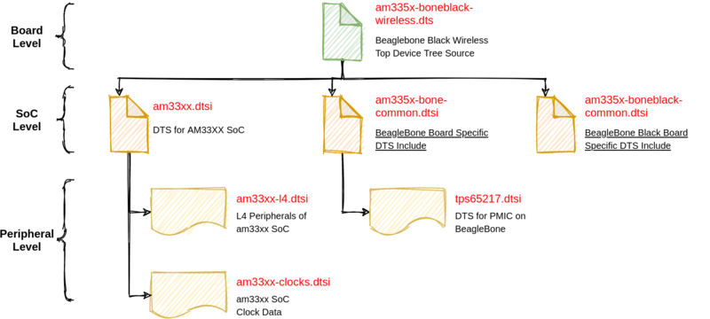
Device Tree Hierarchy
Device Tree Files are not monolithic, they can bbe split into multiple files, and including each other in hierarchy
.dtsi are included files, generally are SoC/Peripheral Level.
.dts are final Device Tress, generally Board Level.
The inclusion works by overlaying the tree of the including file over the tree of the included file.
Simply, Trees defined later in order overlays earlier trees.
Device Tree Source Format
Device Tree Source has JSON like syntax. Device Tree is Tree of Nodes with Node Properties. A node is a device or an IP block, and node properties are device charateristics/specifications. [2]
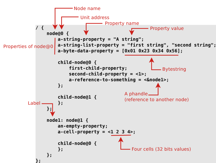
- Node Name : Each node in the devicetree is named according to the following convention:
node-name@unit-address
-
- The node–name component specifies the name of the node.
- The unit–address component of the name is specific to the bus type on which the node sits.
- The root node does not have a node-name or unit-address. It is identified by a forward slash (/).
Q. How does one know how to write the correct nodes/properties to describe a given hardware platform ?
A. The DeviceTree Specifications at https://www.devicetree.org/specifications/ gives the base Device Tree syntax and specifies a number of standard properties.
Device Tree Organization
Under the root of the Device Tree, one typically finds the following top-level nodes.
- A cpus node, which sub-nodes describing each CPU in the system.
- A memory node, which defines the location and size of the RAM.
- A chosen node, which defines parameters chosen or defined by the system firmware at boot time.
In practice, one of its usage is to pass the kernel command line. - A aliases node, to define shortcuts to certain nodes.
- One or more nodes defining the buses in the SoC.
- One or mode nodes defining on-board devices.BeagleBone Black Wireless Root Level Device Tree (Truncated)
/ {
    model = "TI AM335x BeagleBone Black Wireless";
    compatible = "ti,am335x-bone-black-wireless", "ti,am335x-bone-black", "ti,am335x-bone", "ti,am33xx";
    interrupt-parent = <&intc>;
    #address-cells = <1>;
    #size-cells = <1>;

    chosen {
        base_dtb = "am335x-boneblack-wireless.dts";
        base_dtb_timestamp = __TIMESTAMP__;
        stdout-path = &uart0;
    };
    aliases {
        i2c0 = &i2c0;
        serial1 = &uart1;
        usb0 = &usb0;
        ...
    };
    cpus {
        #address-cells = <1>;
        #size-cells = <0>;
        cpu@0 {
            compatible = "arm,cortex-a8";
            device_type = "cpu";
            reg = <0>;
            clocks = <&dpll_mpu_ck>;
            clock-names = "cpu";
            clock-latency = <300000>; /* From omap-cpufreq driver */
            cpu0-supply = <&dcdc2_reg>;
    	};
    };
    memory@80000000 {
        device_type = "memory";
        reg = <0x80000000 0x20000000>; /* 512 MB */
    };
    leds {
        pinctrl-names = "default";
        pinctrl-0 = <&user_leds_s0>;
        compatible = "gpio-leds";

        led2 {
            label = "beaglebone:green:usr0";
            gpios = <&gpio1 21 GPIO_ACTIVE_HIGH>;
            linux,default-trigger = "heartbeat";
            default-state = "off";
        };
    };
    ...
};
All devicetrees shall have a root node, and One /cpus node and At least one /memory node shall be present at the root of all devicetrees.
Device Tree Common Properties
soc {
    compatible = "simple-bus";
    #address-cells = <1>;
    #size-cells = <1>;
    ranges = <0x0 0xe0000000 0x00100000>;
    serial {
        device_type = "serial";
        compatible = "ns16550";
        reg = <0x4600 0x100>;
        clock-frequency = <0>;
        interrupts = <0xA 0x8>;
        interrupt-parent = <&ipic>;
    };
};
compatible
- consists of one or more strings from the most specific to the less specific
- Describes the specific binding to which the node complies.
- It uniquely identifies the programming model of the device.
- Practically speaking, it is used by the operating system to find the appropriate driver for this device.
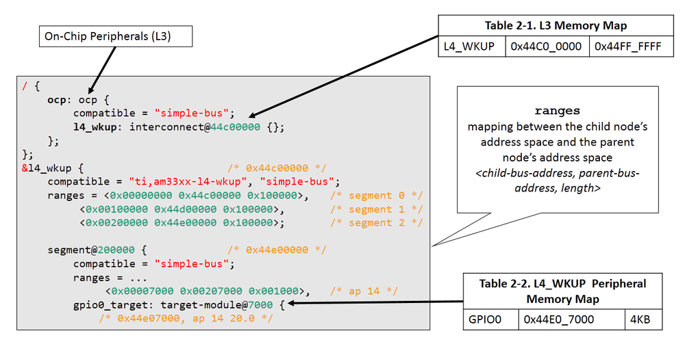
- Special value: simple–bus indicates a bus where all sub-nodes are memory-mapped devices. Generally used for devices inside the SoC.
- When describing real hardware, typical form is manufacturer,model
Examples:
compatible = “arm,armv8-timer”;
compatible = “fsl,mpc8641”, “ns16550”;
status
- okay means the device is present and should be enabled.
- disabled Indicates that the device is not presently operational, but it might become operational in the future
#address-cells and #size-cells
- The #address-cells and #size-cells properties may be used in any device node that has children in the device-tree hierarchy, it describes how child device nodes should be addressed.
- The #address-cells property definesthe number of uint32 cells used to encode the address field in a child node’s reg property.
- The #size-cells property defines the number of uint32 cells used to encode the size field in a child node’s reg property.
- Simply, the #address-cells property indicate how many cells (i.e 32 bits values) are needed to form the base address part in the reg property. The #size-cells is the same, for the size part of the reg property.
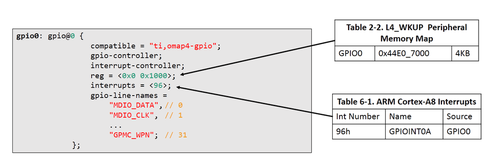
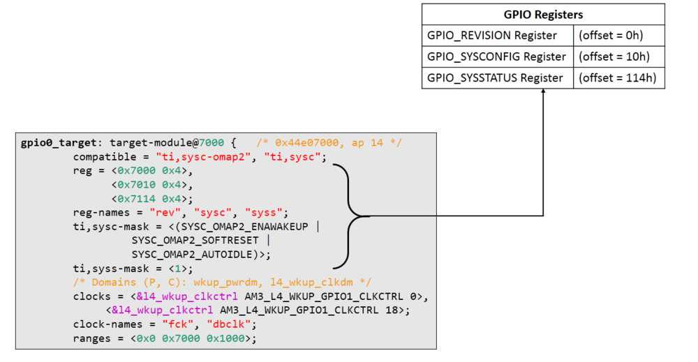
reg
- The reg property describes the address of the device’s resources within the address space defined by its parent bus.
- Encoded as number of (address, length) pairs.
- Memory-mapped devices: base address and size of the registers.
ranges
- The ranges property provides a means of defining a mapping or translation between the address space of the bus (the child address space) and the address space of the bus node’s parent (the parent address space).
- The format of the value of the ranges property is an arbitrary number of triplets of (child-bus-address, parent-bus-address, length)
interrupts, interrupt-parent, interrupt-controller
- The interrupts property of a device node defines the interrupt or interrupts that are generated by the device.
- The interrupt-parent property is a phandle that points to the interrupt controller for the current node.
- The interrupt-controller property is a boolean property that indicates that the current node is an interrupt controller
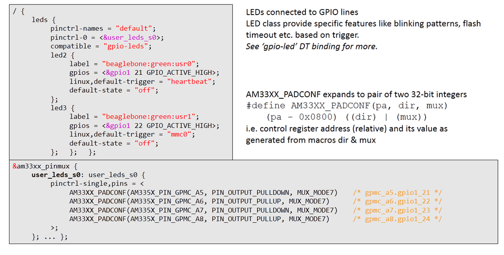
pinctrl-*
- Indicates the pin-muxing configuration requested by the device
clocks
- Which clock(s) are used by the device, from which clock controller
- Which DMA controller and channels are used by the devicedmas
Device Tree Bindings
Q. How specific types and classes of devices are represented in the device tree?
A. Device Tree Bindings
When creating a new device tree representation for a device, a binding should be created that fully describes the required properties and value of the device. This set of properties shall be sufficiently descriptive to provide device drivers with needed attributes of the device.
All Device Tree bindings recognized by the kernel are documented in Documentation/devicetree/bindings.
Each binding documentation described which properties are accepted, with which values, which properties are mandatory vs. optional, etc.
The compatible property of a device node describes the specific binding (or bindings) to which the node complies.
Legacy vs YAML DT Binding : Earlier DT Bindings were defined in Human Readable Text Format. But as device tree compiler only does syntaxic validation, YAML based bingings were introduced to do semantic validation
Legacy DT Binding Example (gpio-omap.txt)
OMAP GPIO controller bindings

Required properties:
- compatible:
  - "ti,omap2-gpio" for OMAP2 controllers
  - "ti,omap3-gpio" for OMAP3 controllers
  - "ti,omap4-gpio" for OMAP4 controllers
- reg : Physical base address of the controller and length of memory mapped
  region.
- gpio-controller : Marks the device node as a GPIO controller.
- #gpio-cells : Should be two.
  - first cell is the pin number
  - second cell is used to specify optional parameters (unused)
- interrupt-controller: Mark the device node as an interrupt controller.
- #interrupt-cells : Should be 2.
  The first cell is the GPIO number.
  The second cell is used to specify flags:
    bits[3:0] trigger type and level flags:
      1 = low-to-high edge triggered.
      2 = high-to-low edge triggered.
      4 = active high level-sensitive.
      8 = active low level-sensitive.
- interrupts : The interrupt the controller is rising as output when an
  interrupt occures

OMAP specific properties:
- ti,hwmods:		Name of the hwmod associated to the GPIO:
			"gpio<X>", <X> being the 1-based instance number
			from the HW spec.
- ti,gpio-always-on: 	Indicates if a GPIO bank is always powered and
			so will never lose its logic state.
Example:
gpio0: gpio@44e07000 {
    compatible = "ti,omap4-gpio";
    reg = <0x44e07000 0x1000>;
    ti,hwmods = "gpio1";
    gpio-controller;
    #gpio-cells = <2>;
    interrupt-controller;
    #interrupt-cells = <2>;
    interrupts = <96>;
};
YAML DT Binding Example (mediatek,mt7621-gpio.yaml)
# SPDX-License-Identifier: GPL-2.0-only OR BSD-2-Clause
%YAML 1.2
---
$id: http://devicetree.org/schemas/gpio/mediatek,mt7621-gpio.yaml#
$schema: http://devicetree.org/meta-schemas/core.yaml#

title: Mediatek MT7621 SoC GPIO controller

maintainers:
  - Sergio Paracuellos <sergio.paracuellos@gmail.com>

description: |
  The IP core used inside these SoCs has 3 banks of 32 GPIOs each.
  The registers of all the banks are interwoven inside one single IO range.
  We load one GPIO controller instance per bank. Also the GPIO controller can receive
  interrupts on any of the GPIOs, either edge or level. It then interrupts the CPU
  using GIC INT12.

properties:
  $nodename:
    pattern: "^gpio@[0-9a-f]+$"

  compatible:
    const: mediatek,mt7621-gpio

  reg:
    maxItems: 1

  "#gpio-cells":
    const: 2

  gpio-controller: true
  gpio-ranges: true

  interrupt-controller: true

  "#interrupt-cells":
    const: 2

  interrupts:
    maxItems: 1

required:
  - compatible
  - reg
  - "#gpio-cells"
  - gpio-controller
  - gpio-ranges
  - interrupt-controller
  - "#interrupt-cells"
  - interrupts

additionalProperties: false

examples:
  - |
    #include <dt-bindings/gpio/gpio.h>
    #include <dt-bindings/interrupt-controller/mips-gic.h>

    gpio@600 {
      compatible = "mediatek,mt7621-gpio";
      reg = <0x600 0x100>;
      #gpio-cells = <2>;
      gpio-controller;
      gpio-ranges = <&pinctrl 0 0 95>;
      interrupt-controller;
      #interrupt-cells = <2>;
      interrupt-parent = <&gic>;
      interrupts = <GIC_SHARED 12 IRQ_TYPE_LEVEL_HIGH>;
    };
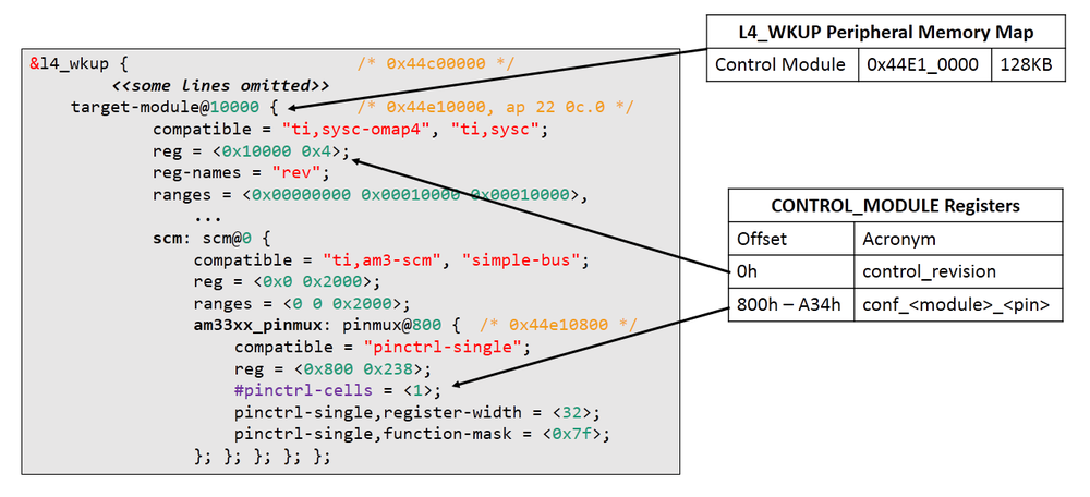
Device Tree and Datasheet Correlation Examples
1. GPIO
2. LED
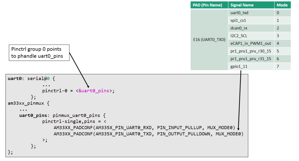
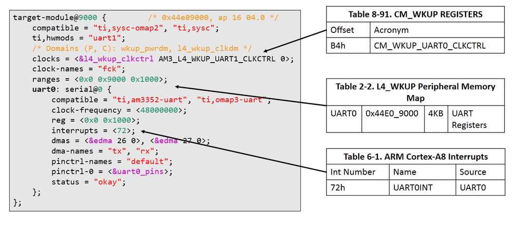
3. UART
How to compile?
On ARM, all Device Tree Source files (DTS) are for now located in arch/arm/boot/dts.
The Device Tree Compiler (DTC) is the tool that is used to compile the source into a binary form. Source code for the DTC is located in scripts/dtc. The Device Tree Blob is produced by the compiler, and is the binary that gets loaded by the bootloader and parsed by the kernel at boot time.
Syntax : dtc [-I <input-format>] [-O <output-format>] [-o output-filename] [-V output_version] input_filename
To Compile DTS to DTB
dtc –I dts –O dtb am335x-boneblack-wireless.dts > am335x-boneblack-wireless.dtb
To reverse compile DTB to DTS
The DTC can also be used to reverse compile DTBs and make them human-readable again. 😄
dtc –I dtb –O dts am335x-boneblack-wireless.dtb > am335x-boneblack-wireless.dts
Q. How to validate Device Tree?
A. dtc only does syntaxic validation. YAML bindings allow to do semantic validation.
make dt_bindings_check : verify that YAML bindings are valid
make dtbs_check : validate DTs currently enabled against YAML bindings
Device Tree & Linux Kernel
Device Tree and U-Boot
U-Boot typically configures using CONFIG options in board config file. But U-Boot can do run-time configuration via flattened device tree (i.e. device tree blob). This feature aims to make it possible for a single U-Boot binary to support multiple boards, with the exact configuration of each board controlled by a flat device tree (fdt).
U-Boot automatically patches the Device Tree Blob passed to Linux
- Sets the RAM base address and size
- Sets the kernel command line arguments
- Sets MAC address for network interfaces
U-Boot itself does not use the device tree normally, although it has several commands that allow you to view and manipulate the FDT itself.
- Using fdt commands: fdt set, fdt mknode, fdt rm
- Using Device Tree Overlays
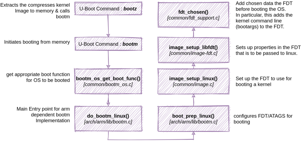
When U-Boot adds cmdline_args i.e. bootargs to device tree?
How and When Linux loads DTB?
There is one single entry point to the kernel, at the start of the kernel image. That entry point supports two calling conventions.
ATAGS interface : Minimal information is passed from firmware to the kernel with a tagged list of predefined parameters.
r0 : 0
r1 : Machine type number
r2 : Physical address of tagged list in system RAM
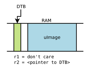
Entry with a flattened device-tree block : Firmware loads the physical address of the flattened device tree block (dtb) into r2, r1 is not used.
r0 : 0
r1 : Valid machine type number. When using a device tree, a single machine type number will often be assigned to represent a class or family of SoCs.
r2 : physical pointer to the device-tree block in RAM. Device tree can be located anywhere in system RAM, but it should be aligned on a 64 bit boundary.
The kernel will differentiate between ATAGS and device tree booting by reading the memory pointed to by r2 and looking for either the flattened device tree block magic value (0xd00dfeed) or the ATAG_CORE value at offset 0x4 from r2 (0x54410001).
Device Tree Blob header is defined in include/linux/of_fdt.h
How Kernel Unflattens DTB to Tree nodes?
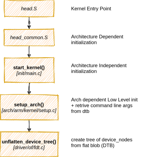
/* head_common.S
 *  r0  = cp#15 control register (exc_ret for M-class)
 *  r1  = machine ID
 *  r2  = atags/dtb pointer
 *  r9  = processor ID
 */
__INIT __mmap_switched:
	/* << Many lines Skipped Here>> */
	b	start_kernel

//start kernel
asmlinkage __visible void __init start_kernel(void) {
	char *command_line;
	...
	setup_arch(&command_line);
	...
}

//setup arch
void __init setup_arch(char **cmdline_p) {
	...
	unflatten_device_tree();
	...
}


// unflatten_device_tree - create tree of device_nodes from flat blob
void __init unflatten_device_tree(void) {
	__unflatten_device_tree(initial_boot_params, NULL, &of_root,
				early_init_dt_alloc_memory_arch, false);

	/* Get pointer to "/chosen" and "/aliases" nodes for use everywhere */
	of_alias_scan(early_init_dt_alloc_memory_arch);

	unittest_unflatten_overlay_base();
}

// __unflatten_device_tree - create tree of device_nodes from flat blob
void *__unflatten_device_tree(const void *blob,
			      struct device_node *dad,
			      struct device_node **mynodes,
			      void *(*dt_alloc)(u64 size, u64 align),
			      bool detached) {

	if (fdt_check_header(blob)) { ... }
    ...
	/* First pass, scan for size */
	size = unflatten_dt_nodes(blob, NULL, dad, NULL);
    ...
	/* Allocate memory for the expanded device tree */
	mem = dt_alloc(size + 4, __alignof__(struct device_node));
    ...
	/* Second pass, do actual unflattening */
	unflatten_dt_nodes(blob, mem, dad, mynodes);
	... }

// unflatten_dt_nodes - Alloc and populate a device_node from the flat tree
static int unflatten_dt_nodes(const void *blob,
			      void *mem,
			      struct device_node *dad,
			      struct device_node **nodepp) {
	...
	for (offset = 0;
	     offset >= 0 && depth >= initial_depth;
	     offset = fdt_next_node(blob, offset, &depth)) {
		if (!IS_ENABLED(CONFIG_OF_KOBJ) &&
		    !of_fdt_device_is_available(blob, offset))
			continue;

		if (!populate_node(blob, offset, &mem, nps[depth],
				   &nps[depth+1], dryrun))
			return mem - base;
        ...
}

//populate_node
static bool populate_node(...) {
	...
	np = unflatten_dt_alloc(mem, sizeof(struct device_node) + allocl,
				__alignof__(struct device_node));
	...
    if (dad != NULL) {
        np->parent = dad;
        np->sibling = dad->child;
        dad->child = np;
    } ...
	populate_properties(blob, offset, mem, np, pathp, dryrun);
	...
}

//populate_properties
static void populate_properties(...);
The defined global pointers in Kernel :
of_root: Pointer to root node structureof_chosen: Pointer to chosen node structureof_aliases: Pointer to aliases node structureof_stdout: Pointer to device node being used for stdout
The Structure of unflattened Device Tree Node in kernel is
struct device_node {
	const char *name;
	phandle phandle;
	const char *full_name;
	struct fwnode_handle fwnode;

	struct	property *properties;
	struct	property *deadprops;	/* removed properties */
	struct	device_node *parent;
	struct	device_node *child;
	struct	device_node *sibling;
	struct	kobject kobj;
	unsigned long _flags;
	void	*data;
};

struct property {
	char	*name;
	int	length;
	void	*value;
	struct property *next;
	unsigned long _flags;
	struct bin_attribute attr;
};
How Kernel Load cmdline_args from dtb?
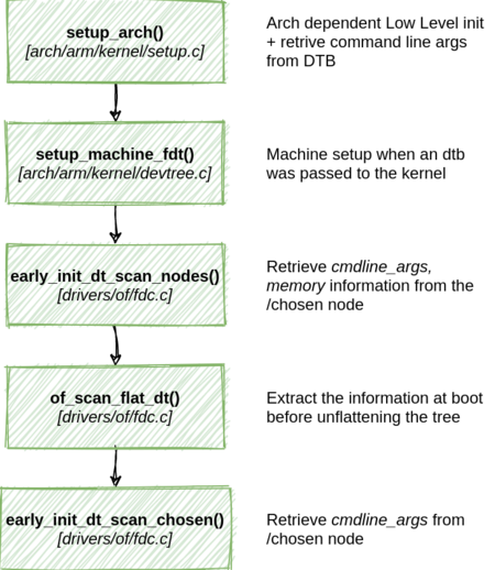
//setup arch
void __init setup_arch(char **cmdline_p) {
	...
	mdesc = setup_machine_fdt(__atags_pointer);
	...
	/* populate cmd_line too for later use, preserving boot_command_line */
	strlcpy(cmd_line, boot_command_line, COMMAND_LINE_SIZE);
	*cmdline_p = cmd_line;
	...
}

//setup_machine_fdt - Machine setup when an dtb was passed to the kernel
const struct machine_desc * __init setup_machine_fdt(unsigned int dt_phys) {
	const struct machine_desc *mdesc, *mdesc_best = NULL;
	...
	early_init_dt_scan_nodes();
	/* Change machine number to match the mdesc we're using */
	__machine_arch_type = mdesc->nr;
	...
}

//early_init_dt_scan_mode
void __init early_init_dt_scan_nodes(void) {
	/* Retrieve various information from the /chosen node */
	rc = of_scan_flat_dt(early_init_dt_scan_chosen, boot_command_line);

	/* Initialize {size,address}-cells info */
	of_scan_flat_dt(early_init_dt_scan_root, NULL);

	/* Setup memory, calling early_init_dt_add_memory_arch */
	of_scan_flat_dt(early_init_dt_scan_memory, NULL);
}

//of_scan_flat_dt - scan flattened tree blob and call callback on each.

//early_init_dt_scan_chosen
int __init early_init_dt_scan_chosen(unsigned long node, const char *uname,
				     int depth, void *data) {
	...
	if (depth != 1 || !data ||
	    (strcmp(uname, "chosen") != 0 && strcmp(uname, "chosen@0") != 0))
		return 0;

	early_init_dt_check_for_initrd(node);

	/* Retrieve command line */
	p = of_get_flat_dt_prop(node, "bootargs", &l);
	if (p != NULL && l > 0)
		strlcpy(data, p, min(l, COMMAND_LINE_SIZE));

	/* No arguments from boot loader, use kernel's  cmdl*/
	if (!((char *)data)[0])
		strlcpy(data, CONFIG_CMDLINE, COMMAND_LINE_SIZE);
	...
}
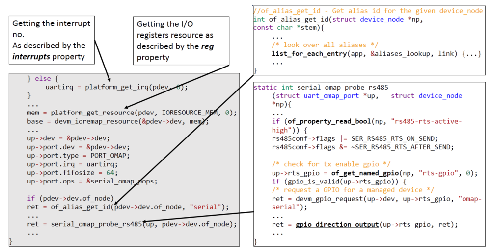
How Kernel use Device Trees?
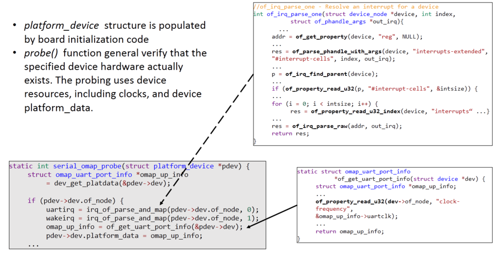
Platform devices are devices that typically appear as autonomous entities in the system. This includes legacy port-based devices and host bridges to peripheral buses, and most controllers integrated into system-on-chip platforms. What they usually have in common is direct addressing from a CPU bus. Rarely, a platform_device will be connected through a segment of some other kind of bus; but its registers will still be directly addressable.
Binding To Driver
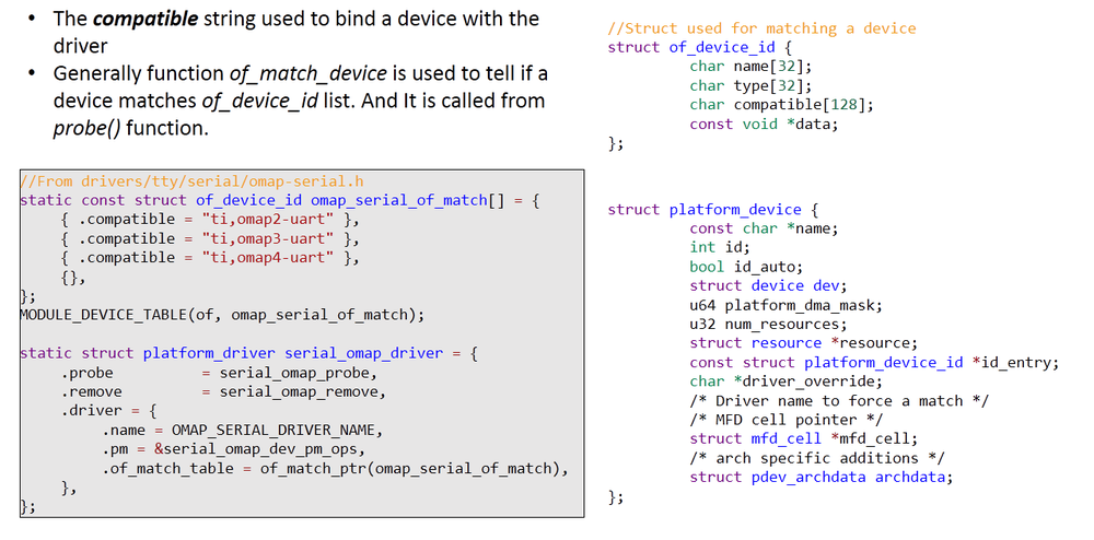
Device Probe
Device Tree at Runtime
Unflattened Device Tree can be visualised in file like form at path `/proc/device-tree
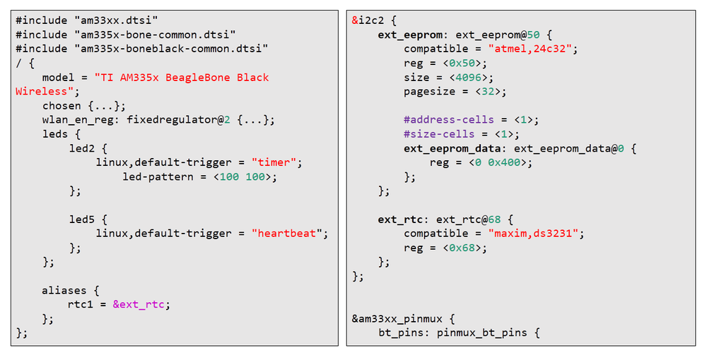
BeagleBone Device Tree Hacking
Device Tree Hacking Demos
- LED Trigger Hack
- Changing Heartbeat from LED USR0 to LED USR3
- Changing Trigger of USR0 LED to “timer” with Ton=100ms and Toff=100ms
- Adding I2C EEPROM (24c32) device to Device Tree & BeagleBone Black
- Adding I2C RTC (ds3231) device to Device Tree & BeagleBone Black
I2C EEPROM & I2C RTC are connected to BeagleBone I2C2 (Header P9 19 & 20)
Modified Device Tree
am335x-boneblack-wireless.dts was modified for the hack as below.
References
- AM335x ARM ® CortexTM-A8 Microprocessors – Technical Reference Manual – SPRUH73H – April 2013
- Devicetree Specification – Release v0.2 – 20 December 2017 – www.devicetree.org
- Power.org™ Standard for Embedded Power Architecture™ Platform Requirements (ePAPR) – Version 1.1 – 08 April 2011 – elinux.org/images/c/cf/Power_ePAPR_APPROVED_v1.1.pdf
Recent Comments