
Objective
The objective of this mini project is to create a mini-game similar to the 1976 atari breakout game using beagle-bone wireless, 128×64 GLCD and GPIO push buttons. This would include developing linux drivers for kernel space and a user-level application to run the game.
GLCD Hardware
The 128×64 GLCD consists of 20 pins whose details are as given below
| Pin Number | Symbol | Functionality |
| 1 | VSS | Ground |
| 2 | VCC | +5V |
| 3 | Vo | Contrast Adjustment |
| 4 | RS/DI | Register Select/Data Instruction. 0:Instruction,1:Data |
| 5 | R/W | Read/Write, 0:Write,1:Read |
| 6 | EN | Enable, Falling Edge Triggered |
| 7 | D0 | Data Bit 0 |
| 8 | D1 | Data Bit 1 |
| 9 | D2 | Data Bit 2 |
| 10 | D3 | Data Bit 3 |
| 11 | D4 | Data Bit 4 |
| 12 | D5 | Data Bit 5 |
| 13 | D6 | Data Bit 6 |
| 14 | D7 | Data Bit 7 |
| 15 | CS1 | Chip Select For IC1 |
| 16 | CS2 | Chip Select For IC2 |
| 17 | RST | RST, Reset |
| 18 | VEE | Outputs Negative Voltage used for Contrast Adjustment |
| 19 | LED+ | Back-Light Anode(+) |
| 20 | LED- | Back-Light Cathode(-) |
The details of the pin are as given below –
- The VSS and VCC pins are used to supply power to the GLCD and are connected to ground and +5V respectively.
- Vo pin is used to adjust GLCD contrast by connecting this pin to potentiometer’s wiper whose other pins are connected to VCC and VEE of GLCD.
- RS/DI pin is used to select between data register(to input 8 bit pixel value) or instruction register(to input commands) of GLCD
- EN pin is triggered on falling edge of voltage which signals GLCD to intake intake data bits, RS/DI bit and RW bit.
- D0-D7 are the data bits of GLCD
- CS1, CS2 are the chip select bits to select between the left and right windows. CS1 selects left window of GLCD while CS2 selects right window of GLCD
- RST is the reset pin. It is active low. So giving low voltage to it would reset the whole GLCD. It must be connected to high voltage while using the GLCD
- VEE pin of GLCD generates negative voltage. This pin is generally used along with Vo pin for contrast adjustment.
- LED+ and LED- pins are connected to +5V and ground respectively, to enable backlight.
The functionalities of GLCD are as given below –
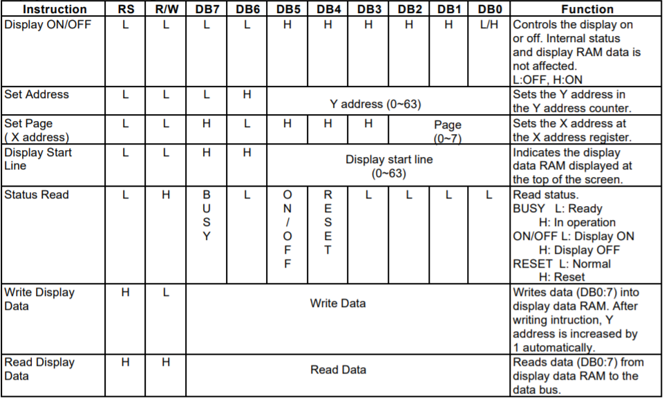
Courtesy: KS0108B Datasheet – Samsung semiconductor
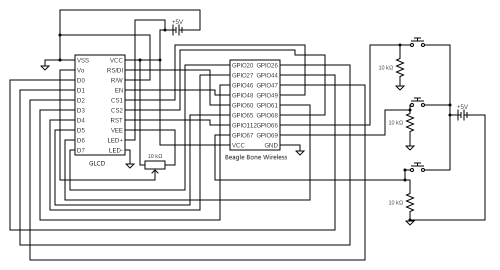
Schematic Diagram
The schematic diagram of the GLCD connection is as given as below –
Driver Development
Separate linux drivers would need to be created for –
- 128×64 GLCD
- GPIO push buttons
The GLCD driver is needed for displaying game and GPIO push buttons to control the in-game movements. A basic tutorial for linux driver development is given in link 1 and link 2
GLCD Driver
The GLCD driver, apart from containing init and exit modules, it also utilizes ioctl calls to carry out functionalities of GLCD as mentioned in table above in the GLCD Hardware section. The GLCD driver module has the following functions with its own functionalities –
- static int __init lcd_init(void) – device registration, gpio pin validity checking and gpio pin initialization to output.
- static void __exit lcd_exit(void) – freeing the gpio pins
- static int lcd_open(struct inode* , struct file* ) – An element of file_operations structure. Initializes GLCD by resetting and then turning on the GLCD display. The user space process pid information is obtained by using get_current() function.
- static long lcd_ioctl(struct file* , unsigned int , unsigned long ) – An element of file_operations structure which handles ioctl calls from user space. Depending on the arguments it selects amongst whether to send commands to GLCD, send data to GLCD, select GLCD window or reset the whole GLCD.
- void lcd_command(int ) – Sends commands(as given in table above in GLCD Hardware section) to GLCD by setting the GLCD data pins with command value, setting RS=0 and making E pin high and then low (Falling edge triggered).
- void lcd_data(int ) – Sends data(as given in table above in GLCD Hardware section) to GLCD by setting the GLCD data pins with data value, setting RS=1 and making E pin high and then low (Falling edge triggered).
- void window_select(int ) – Selects GLCD window, depending on the given argument as below –
- CS1 = 1, CS2 = 0 – Select left window
- CS1 = 0, CS2 = 1 – Select right window
- CS1 = 1, CS2 = 1 – Select both windows
- CS1 = 0, CS2 = 0 – Unselect both windows
- void display_reset(void ) – Reset GLCD display by making RST pin low(Active low pin), wait and then make RST pin high.
GPIO Driver
The GPIO driver carries out interrupt handling when push button is pressed. The interrupt handler sends signals from kernel space to user space on button presses using the send_sig_info() function. The GPIO driver module has the following functions with its own functionalities –
- static int __init button_init(void) – Check validity of GPIO pins, set direction of all the pins as input, debounce the pins and attach separate interrupt handlers to each pin.
- static void __exit button_exit(void) – Free the GPIO pins and free the IRQs.
- irq_handler_t button_handler_<k> (k = 0,1,2) – There are three GPIO interrupt handlers. The respective interrupt handler is invoked on a button press, where it sends signals to user space process. The signal contains values specific to GPIO interrupt. The user space process pid information is present in task_struct structure which is obtained by using get_current() function in GLCD driver.
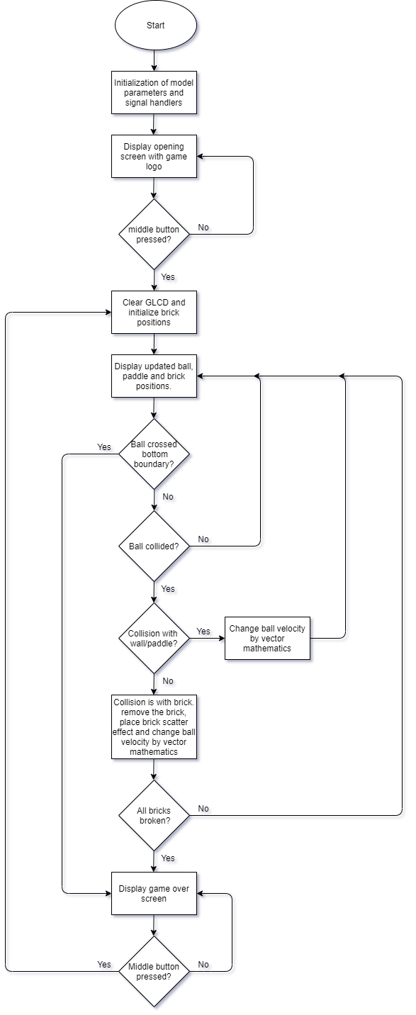
User Space Application & Algorithm
The user space application contains the core logic for the “Break It” game based on the old atari breakout game. This game currently has only one level . The following flowchart describes the algorithm-
The core game logic can be broken down as follows –
- Collision Detection – collision detection is implemented in collision_detect() function. The collision detection algorithm works by detecting if the ball is in the vicinity of the wall/paddle/brick by continuously measuring the displacement between ball center and paddle center, and also between ball center and all the brick centers throughout the frames. If the displacement is lesser than a particular threshold, then a collision is detected.
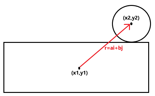
- Once collision is detected, the ball velocity has to be updated. To do this we make use of vectors and find the relative displacement of ball center with respect to paddle/brick center. In such breakout games, the rebound direction of ball itself depends on where it hits the paddle/brick. For this game, the programming is done such that rebound direction is in direction towards relative displacement of ball center with respect to paddle/brick. It is depicted as below
- Once ball has collided with paddle/brick, the new x component of ball velocity and new y component of ball velocity is given by –
- x component of ball velocity = a/(a^2 + b^2)
- y component of ball velocity = b/(a^2 + b^2)
- After collision with brick, the brick is made to vanish and a scatter object is placed below it.
- On the other hand, when ball collides with wall, only one of the velocity component is reversed as follows –
- Ball collides with upper wall, then reverse y component of ball velocity
- Ball collides with left or right wall, then reverse x component of ball velocity
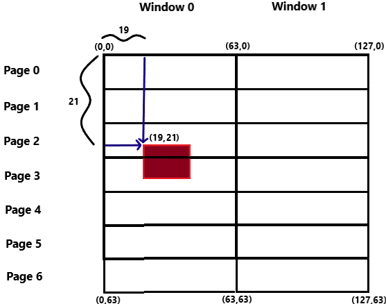
- Frame Buffer, Model Object & Placing Objects in Frame – place_frame_obj() is the core function which utilizes the linear array model data formatted for the GLCD (that displays 8 pixel at a time) and places the model object onto the GLCD. The model object is placed onto the GLCD display by giving x,y coordinates where y coordinates increases downwards of GLCD and x coordinate increases rightwards of GLCD. The top left corner of GLCD is taken as the origin. Now if the y coordinate argument is not a multiple of 8, then the 8 bit value has to be formatted furthermore so that the model object could be split and placed properly into the GLCD pages (The formatting algorithm assumes that model object is small and can atmost occupy 2 pages only). An example is given below –
- Here the y values is 21 which in binary format is 0b010101. Now the most significant 3 bits is 0b010 which means the object is placed in page 2 and least significant 3 bits is 0b101 which means the object is to placed in page 2 shifted downwards by 5 pixels. Hence each 8 bit pixel of model object is shifted to down by 5 bits and placed in page 2. The remaining (8 – pixel shift value) = 8 – 5 = 3 most significant bits of each 8 bit pixel is shifted up by 3 bits and placed in subsequent page which is page 3 here.
- The objects are first placed into a frame buffer before displaying onto the GLCD, which must be updated in a super loop. The paddle position is updated by interrupts.
- Here the paddle , brick and ball have different objects with their own array of 8 bit pixel value.
- Hence to do this, the most significant 3 bits of y coordinate contains information about the the location of page and least significant 3 bits of y coordinate contains pixel shifting information.
- Frame Image Display – Images like opening screen ‘Break It’ logo and game over images are displayed onto the GLCD by converting RGB image into a monochrome bitmap image and then scaling them to atmost 128×64 using a software like GIMP. Before inputting pixel data into GLCD, we must understand that GLCD takes 8 pixels at a time and displays onto the GLCD. Hence, we must format the pixel data of monochrome bitmap image by iterating across the width of the bitmap image and storing 8 pixels of each column at a time into a linear array. Once the end of width has been reached, the algorithm loops back to the starting of width shifting downwards by 8 pixels and restarts doing the same thing till the entire height is covered. An example is given below
- Once the image is formatted for the GLCD, its stored in a linear array which is passed to place_frame_image() function to place the image onto the GLCD by iterating through the linear array by utilizing place_frame_obj() function.
Future Work
- Currently only one level has been added, more levels could be added
- Environment of the game could be made more elegant by adding static backgrounds
- To make the game more dynamic and immersive, power drops could also be added.
Recent Comments