
Specifications
Develop software driver that will allow application to interface with character LCD (Liquid Crystal Display) modules. This software package should work with just about any character module based on the HitachiHD44780_LCD_Controller Dot Matrix LCD Controller & Driver. The module should allow to:
- Control LCD modules containing up to 80 characters.
- Display ASCII characters.
- Display ASCII strings.
- Define up to eight symbols based on a 5×7 dot matrix.
- Display bargraphs.
- The module should assume the presence of a real-time kernel
- The driver should make use of a binary semaphore to prevent multiple tasks from accessing the display at the same time.
LCD Modules
A character module contains the LCD and the drive electronics. Character displays are composed of one to four lines each having between 16 and 40 character blocks. Each character block consists of a 5×8 dot matrix which is used to display any ASCII character and a limited number of symbols. Character modules generally have at least one thing in common: they pretty much all use the Hitachi HD44780 LCD module controller. The HD44780 can interface directly with any 4- or 8-bit data bus, draws very little current (less than 1 mA), is fully ASCII-compatible, can display up to 80 characters, and contains eight user-programmable 5×8 symbols.
The hardware interface of an LCD module is quite straightforward. LCD modules can generally interface directly with most microprocessor buses either as an I/O device or a memory mappedI/O. The HD44780 has a 500 nS (nano-second) access time.
Interfacing to an LCD module
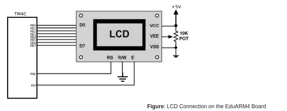
Jumper Selection:
J5 – Short 3 & 4
The HD44780 takes a certain amount of time to process commands or data sent to it. The Hitachi data sheet provides us with the maximum amount of time required for each type of data transfer. Because of this, the software can simply send a command or data and wait at least the amount of time specified before sending the next command or data. Note that the HD44780 itself allows the microprocessor to read a BUSY status. The BUSY status can be read by the microprocessor to determine if the HD44780 is ready to accept another command or more data. We should make use of the BUSY capability of the HD44780 because this provides us with a true indication that the HD44780 is ready to accept another command or more data.
With the hardware interface shown above , the LCD module appears as two write-only registers (note that the R/W line is always low). The first write register is called the data register (when RS is high) while the other write register is called the instruction register (when RS is low). Characters to display are written to the data register. The control register allows the software to control the operating mode of the module: clear the display, set the position of the cursor, tum the display ON or OFF, etc.
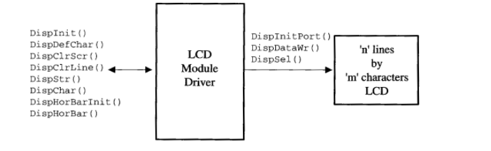
LCD driver block diagram
The module should assume the presence of a real-time kernel because it requires a semaphore and time delay services. The display module should make use of a binary semaphore to prevent multiple tasks from accessing the display at the same time. Use of the semaphore should be encapsulated in the code, so that, application doesn’t have to worry about it.
LCD Display Configuration
You need to adapt three hardware interface functions to the hardware environment. To make this module as portable as possible, access to hardware ports have to be encapsulated into the following functions:
DispInitPort(), DispDataWr(), and DispSel() (described as follows):
- DispInitPort() is responsible for initializing the output ports used to interface with the LCD module. DispInitPort() is called by DispInit().
- DispDataWr() is used to write a single byte to the LCD module. Depending on the state of the RS line, the byte will be either sent to the data (RS is 1) or control register (RS is 0).
- Changing the state of the RS line is the responsibility of the function DispSel(). DispSel() is called by the LCD display module with one argument that can either be set to DISP_SEL_CMD_REG or DISP_SEL_DATA_REG.
/* Local Constants */
/* ---------------------- HD44780 Commands -------------------- */
#define     DISP_CMD_CLS    0x01   /* Clr display : clears display and returns cursor heme */
#define     DISP_CMD_FNCT   0x3B   /* Function Set: Set 8 bit data length, 1/16 duty, 5x8 dots */
#define     DISP_CMD_MODE   0x06   /* Entry mode: Inc. display data address when writing */
#define     DISP_CMD_ON_OFF 0x0C   /* Disp ON/OFF: Display ON, cursor OFF and no BLINK character */

#define     DISP_SEL_CMD_REG   0
#define     DISP_SEL_DATA_REG  1

/* Local Variables */
static uint8_t  DispMaxCols;       /* Maximum number of columns (i.e. characters per line) */
static uint8_t  DispMaxRows;       /* Maximum number of rows for the display */

static  uint8_t LCDBar1[] = {0x10, 0x10, 0x10, 0x10, 0x10, 0x10, 0x10, 0x10};
static  uint8_t LCDBar2[] = {0x18, 0x18, 0x18, 0x18, 0x18, 0x18, 0x18, 0x18};
static  uint8_t LCDBar3[] = {0x1C, 0x1C, 0x1C, 0x1C, 0x1C, 0x1C, 0x1C, 0x1C};
static  uint8_t LCDBar4[] = {0x1E, 0x1E, 0x1E, 0x1E, 0x1E, 0x1E, 0x1E, 0x1E};
static  uint8_t LCDBar5[] = {0x1F, 0x1F, 0x1F, 0x1F, 0x1F, 0x1F, 0x1F, 0x1F};

/* Arrows */
const uint8_t LCDRightArrowBuf[] = {0x08, 0x0C, 0x0E, 0x1F, 0x1F, 0x0E, 0x0C, 0x08};
const uint8_t LCDLeftArrowBuf[] = {0x02, 0x06, 0x0E, 0x1F, 0x1F, 0x0E, 0x06, 0x02};
const uint8_t LCDUpArrowBuf[] = {0x04, 0x0E, 0x0F, 0x04, 0x04, 0x04, 0x04, 0x04};
const uint8_t LCDDownArrowBuf[] = {0x04, 0x04, 0x04, 0x04, 0x04, 0x1F, 0x0E, 04};
API Functions
DispChar()
void DispChar(uint8_t row, uint8_t col, char c);
DispChar() allows you to display a single character anywhere on the display.
Arguments:
row and col will specify the coordinates (row, col) where the character will appear. rows (i.e., lines) are numbered from 0 to DispMaxRows – 1, and columns are numbered from 0 to DispMaxCols – 1. c is the character to display. The Hitachi HD44780 allows you to specify up to eight characters or symbols numbered from 0 to 7 (i.e., its identification). You display a user-defined character or symbol by calling DispChar( ), the row/column position, and the character or symbol’s identification number.
Return Value: None
DispClrLine( )
void DispClrLine(uint8_t line);
DispClrLine() allows your application to clear one of the LCD module’s lines. The line is basically fined with the ASCII character ” (i.e., Ox20).
Arguments: line is the line (i.e., row) to clear. Note that lines are numbered from 0 to DispMaxRows – 1.
Return Value: None
DispClrScr( )
void DispClrScr(void);
DispClrScr() allows you to clear the screen. The cursor is positioned on the top leftmost character. The screen is basically filled with the ASCII character’ , (i.e., Ox20).
Arguments: None
Return Value: None
DispDefChar( )
void DispDefChar(uint8_t id, uint8_t *pat);
DispDefChar() allows you to define up to eight custom 5×8 pixel characters or symbols. This is one of the most powerful features of the LCD modules because it allows you to create graphics such as icons, bargraphs, arrows, etc.
All you need to do to define a new character or symbol is to declare an initialized array of uint8_t containing eight entries and call DispDefChar().
Arguments:
id specifies an identification number for the new character or symbol (a number between 0 and 7). The identification number will be used to actually display the new character or symbol. pat is a pointer to the bitmap table which defines what the character or symbol will look like.
Return Value: None
DispHorBar( )
void DispHorBar(uint8_t row, uint8_t col, Iuint8_t val);
You can use the LCD module to create remarkably high quality bargraphs. The linear bargraph is an excellent trend indicator and can greatly enhance operator feedback. Depending on the size of the module, many bargraphs can be simultaneously displayed. The LCD module software allows you to display bargraphs of any size anywhere on the screen.
DispHorBar () is used to display horizontal bars anywhere on the screen.
Arguments: row and col will specify the coordinates (row, col) where the first character in the bargraph will appear. rows (i.e., lines) are numbered from to DispMaxRows – 1, and columns are numbered from 0 to DispMaxCols – 1.
val is the number of bars you want to have turned on (a number between 0 to 80 in this example).
Return Value: None
DispHorBarInit( )
void DispHorBarInit(void) ;
DispHorBarInit() defines five special symbols with identification numbers I through 5. You must be call before you use DispHorBar( ). You only need to call DispHorBarInit( ) once unless you intend to redefine the symbol identifiers dynamically for other purposes.
Arguments: None
Return Value: None
DispInit()
void Displnit(uint8_t maxrows, uint8_t maxcols);
DispInit() is the initialization code for the module and must be invoked before any of the other functions. DispInit() assumes that multitasking has started because it uses services provided by the real-time kernel.
DispInit() initializes the hardware, creates the semaphore, and sets the operating mode of the LCD module.
Arguments: maxrows is the LCD module’s maximum number of rows (lines), and maxcols is the maximum number of columns (characters per line).
Return Value: None
DispStr()
void DispStr(uint8_t row, uint8_t col, char *s);
DispStr() allows you to display ASCII strings anywhere on the display. You can easily display either integer or floating-point numbers using the standard library functions itoa(), ltoa(), sprintf(), etc. Of course, you should ensure that these functions are reentrant if you are using them in a multitasking environment.
Arguments: row and col will specify the coordinates (row, col) where the first character of the ASCII string will appear. Note that rows (i.e., lines) are numbered from 0 to DispMaxRows – 1. Similarly, columns are numbered from 0 to DispMaxCols – 1. The upper-left corner is coordinate 0, 0.
s is a pointer to the ASCII string. The displayed string will be truncated if the string is longer than the available space on the specified line.
Return Value: None
Recent Comments