
I Problem Statement
To build a CAN bus data-logger using TM4C123GH6PM micro-controller.
II Introduction
CAN bus is a robust automotive communication standard which defines both the protocol and physical layer specifica-
tions for use in vehicles for communication between different sub-systems of the vehicle. It uses differential signalling
to provide immunity from common-mode while still support data rates as high as 1Mbps. The standard defines max-
imum node count of 82 on a single CAN bus. For debugging communication on such bus protocols, a data-logger can
be very handy as it can snoop and store the messages sent over the bus by all the nodes and so debugger need not be
attached to individual nodes. Also, such logger can be used as for telemetry storage.
III Implementation
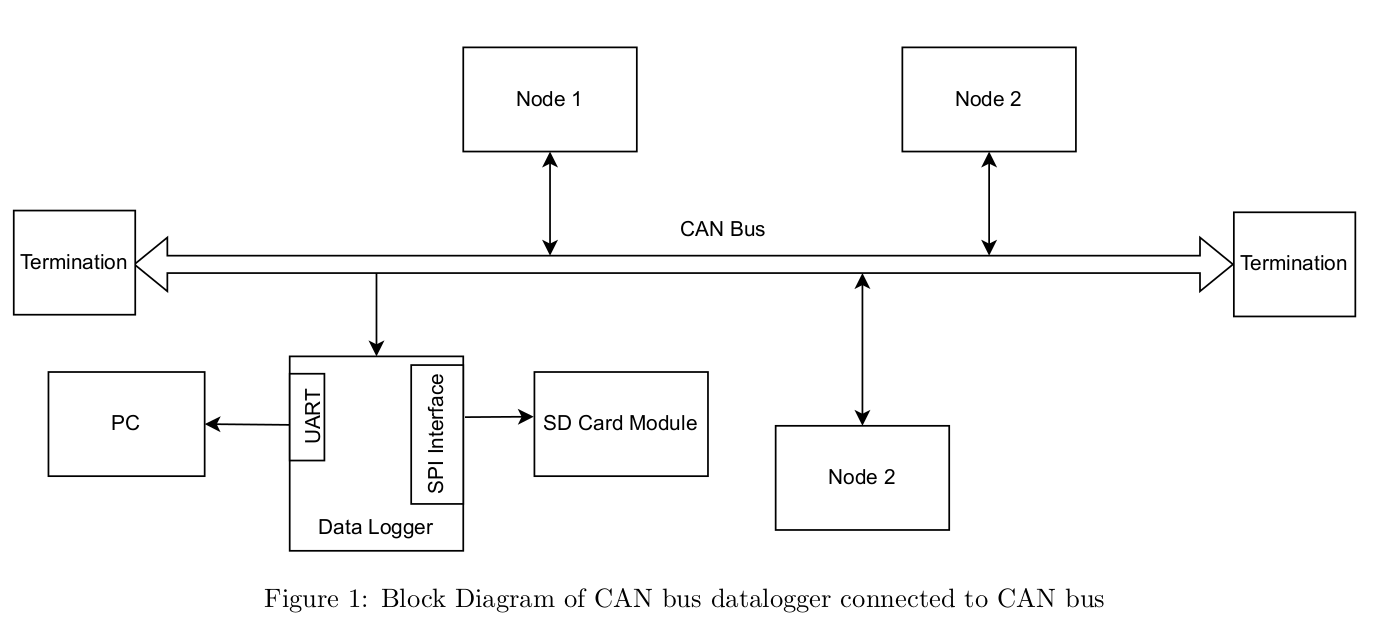
Figure 1 shows the block diagram of a data-logging application on CAN bus. Various components used in implementing
the same are :
Nodes: These are CAN nodes with CAN transceivers and micro-controllers which talk to each other using CAN
protocol. Each node is bi-directional and can contest for bus depending on its identifier.
Termination: CAN bus is terminated on both extremes of the cable to prevent reflections.
Datalogger: A special node that receives messages from all the other nodes on the bus and records them in a SD
card and also dumps them to PC over UART. The data-logger consistos of following imporatant blocks
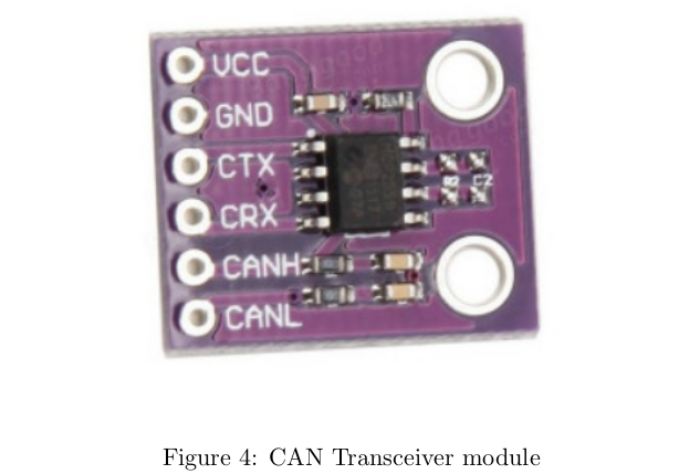
1. CAN Transceiver module: This module is used to translate CAN bus Tx and Rx signals into waveforms
compatible to CAN bus protocol. These are physical layer devices. In the mini-project MCP2551 module
was used (Figure 4).
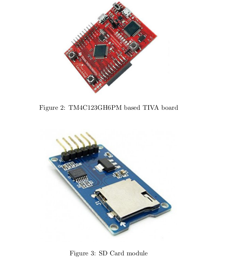
2. Development board: TIVA board based on TM4C123GH6PM micro-controller was used for reading data
from the can bus and logging as well as diplaying on PC using UART peripheral. (Figure 2)
3. SD Card module: For storing the data received from CAN bus, SD card module was used along with SPI
peripheral to write raw bytes to a hex file. (Figure 3)
For demo purposes, two nodes were implemented namely (i) Tx Node and (ii) Data-logger node which are discussed
in subsequent sections.
IV Tx Node Schematic
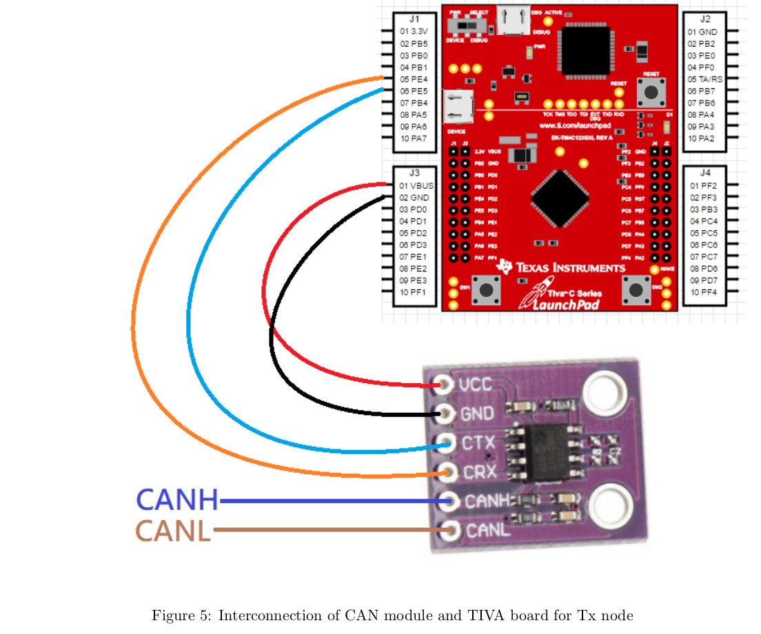
Figure 5 shows the connection of CAN transceiver module to TIVA board for implementing the Tx node. Note that
depending on the datarate, 120 Ohm resistor may be required on CAN bus port. The connections are made inorder
to facilitate using CAN0 module on the TIVA board on pins PE4 and PE5.
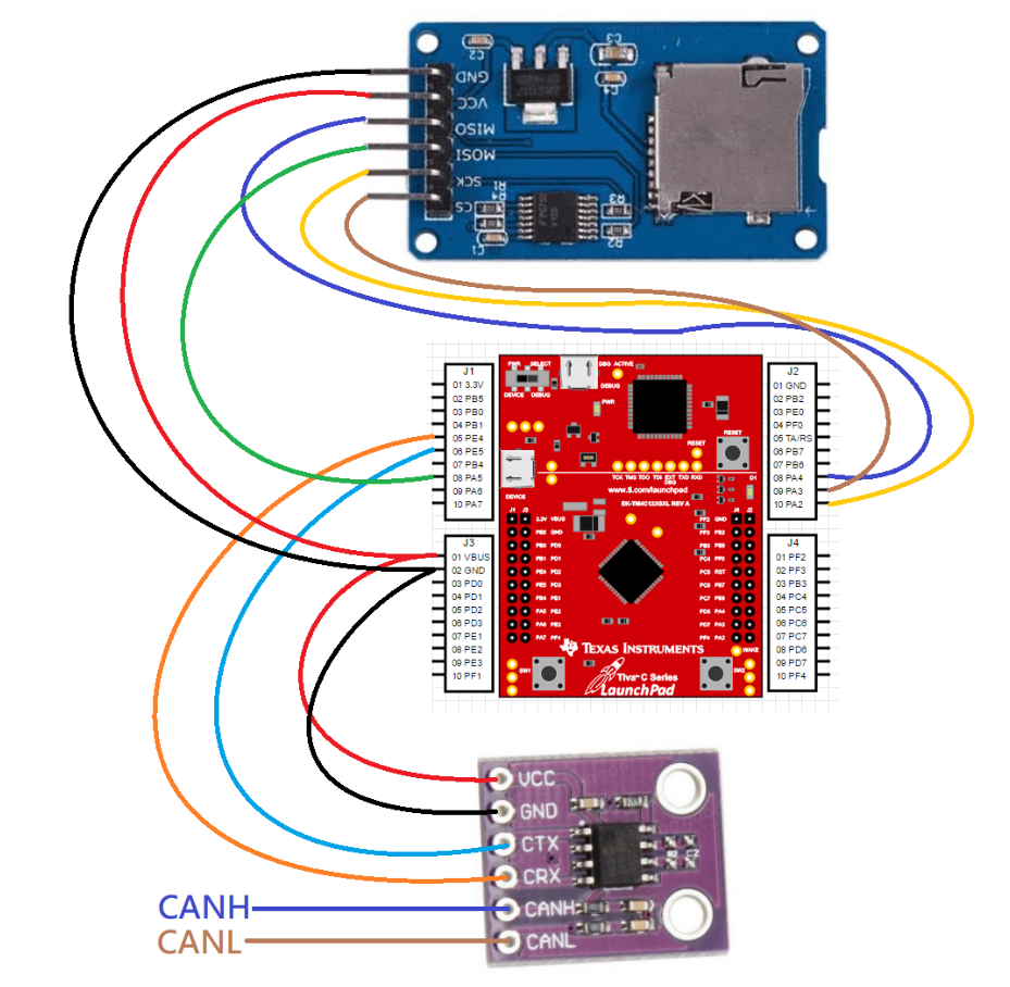
V Data-logger Node Schematic
Figure 6 shows the connection of CAN transceiver module and SD card module to TIVA board. Note that depending
on the datarate, 120 Ohm resistor may be required on CAN bus port. The connections are made inorder to facilitate
using CAN0 module on the TIVA board on pins PE4 and PE5 and SSI0 module on pins PA2 to PA5. Note that
the module used and shown here did not have pull-up resistor on chip select (CS) pin which is required. Populate a
10kOhm pull-up resistor if required.
VI Demo Setup
The node schematics discussed in preceeding sections were soldered on general pupose board to make a hat for the
TIVA board to facilitate reliable transmission of high speed signal from/to CAN moule and SD card module. Figure
7 shows the hat for tx node where as Figure 8 shows the hat for data-logger node both of which are mounted on their
respective TIVA boards.
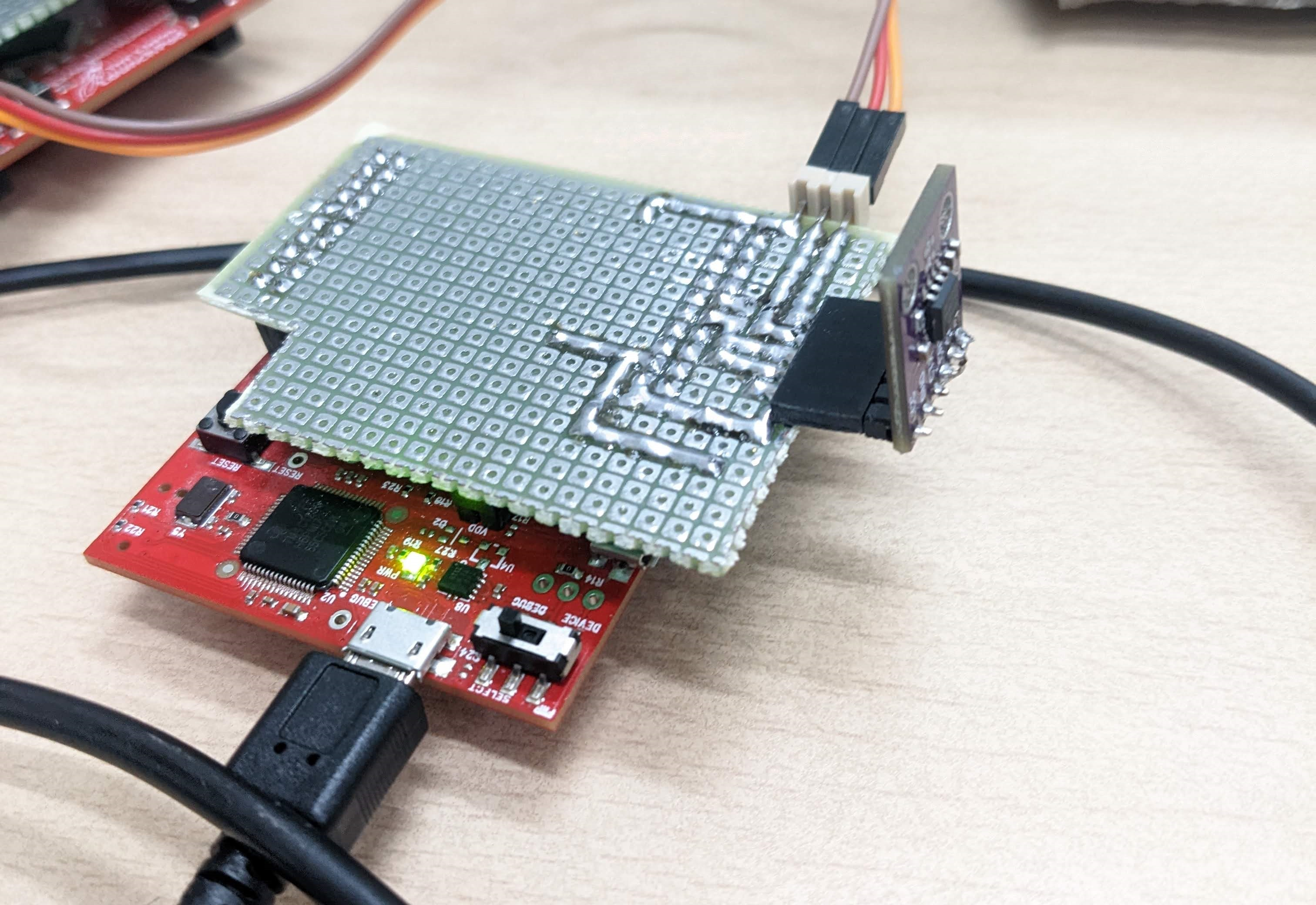
Figure 7: Tx hat for CAN transmitter node
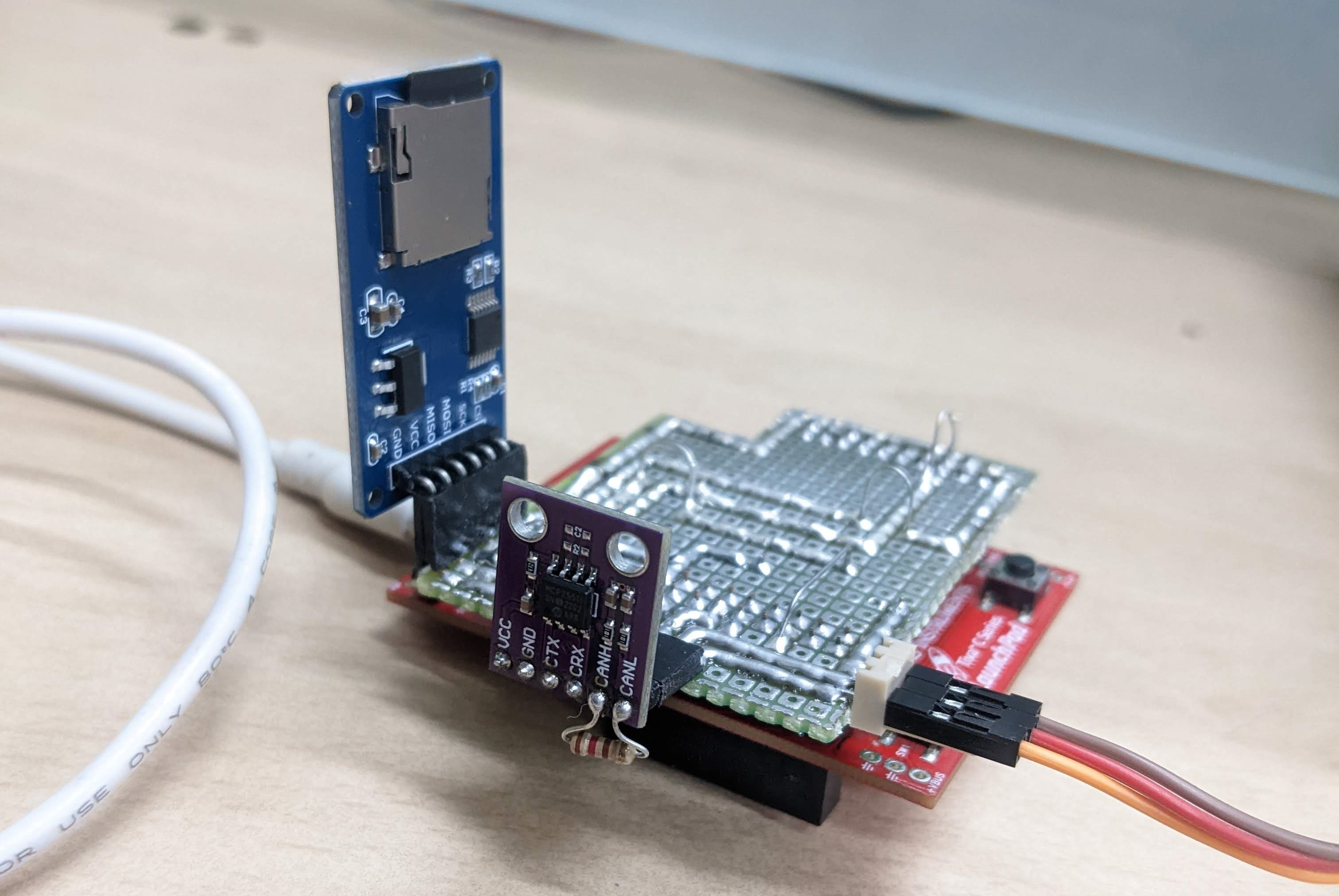
Figure 8: SD hat for CAN bus data-logging node
VII Demo Steps
1. Connect MCP2551 and SD card module to data logging TIVA board and MCP2551 module to transmit node
TIVA board.
2. Format a 16GB SD card with FAT32 file system and insert in the SD card module.
3. Connect the CANH, CANL and GND of the two CAN modules (Place 120 ohm resistors on each side).
4. Open projects sd card logger and can tx node in ccs and flash the code on the two TIVA boards.
5. Open two serial terminals in CCS for the two tiva boards and hit reset button on both the boards.
6. When any key is pressed on the Tx console, it gets transmitted via CAN and is read by the data logging node.
7. The data logging node prints the values on serial console as well as saves in a file CAN dlog .hexin the SD card
which can be read in PC using a hex editor.
VIII Future Scope
Currently the file system implementation does byte wise writes to SD card which is not optimum.
DMA with suitable buffer size can be used to facilitate more efficient transfers and potentially higher throughput
without packet loss.
File management is rudimentary and can be modified to facilitate unique file names instead of over-writing existing
file
Demo: Demo video
Code:codefile
Recent Comments