
Abstract:
Regenerative braking is a unique technique that is used in EVs to capture energy
that the vehicle has due to its motion or, in other words, its kinetic energy that
would have been wasted when the vehicle decelerates or comes to a standstill
while braking.
There are two types of charging methods:
1) Constant current: Constant-current charging simply means that the charging
current supplied is relatively uniform current.
2) Constant voltage:
Constant voltage charging is a method of charging at a constant voltage to
prevent overcharging.
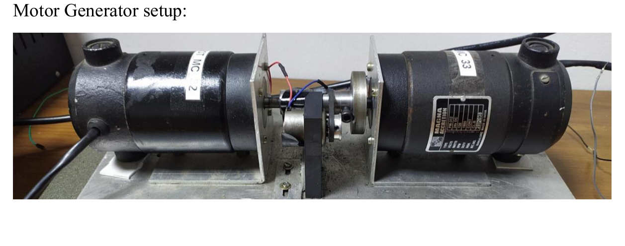
Constant current implementation using TIVA board:
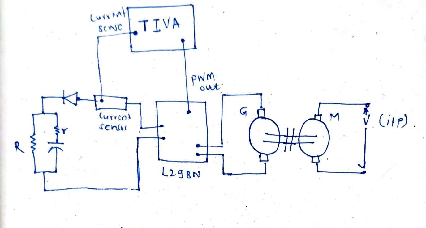
Here we are using motor generator coupled setup. When input voltage is
decreased (breaking condition) motor speed decreases which results in decrease
in voltage at output of generator. L298N takes input as voltage of generator and
PWM from TIVA board. From its output Capacitor is getting charged. R
resistance is for representing load on capacitor to discharge it. Diode is used for
avoiding reverse flow of current from capacitor to ICs. Current sensor in series
path senses the current from the output path and give as input to TIVA board.
Based on deviation of current from set value using PI controller algorithm a
PWM is generated and given back to L298N to get constant current flowing.
Constant Voltage implementation using board:
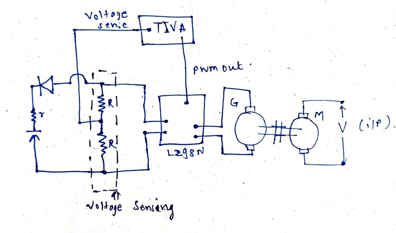
Here we are using same motor generator coupled setup. When input voltage is
decreased (breaking condition) motor speed decreases which results in decrease
in voltage at output of generator. L298N takes input as voltage of generator and
PWM from TIVA board. From its output Capacitor is getting charged. Diode is
used for avoiding reverse flow of current from capacitor to ICs. Very high value
of R is used to make voltage sensing circuit as shown in figure above. Here
sensed voltage at center of voltage divider is given to TIVA board to process.
Using linear mapping PWM signals are generated to get required output
voltage.
Components used:
1.DC Motor-Generator pair with coupling/flywheel.
2.Current sensor ACS712
3.L2918N
4. TIVA board.
5. Diode
6. LCD
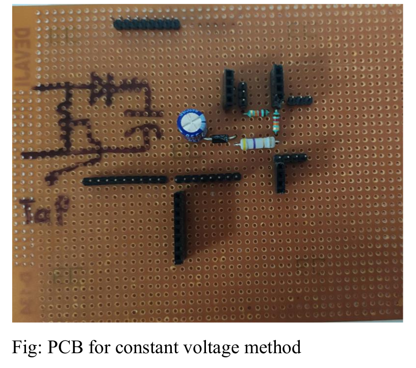
7.RC charging discharging as alternative to a Battery shown as below.
Algorithm:
1. The ACS712 sensor converts the current value into proportional voltage, it is
then given to the ADC module of the TIVA C board.
2. TIVA Microcontroller calculates the error term of the expected current and
the current value at present.
3. This error is given to PI block which calculates the PWM to be given to the
Gate pin of L2918N. The behaviour of the system was checked for different
gains and fined tuning was ensured to reduce response time.4. The required current is asserted and the values of real time current and output
voltage is displayed on LCD.
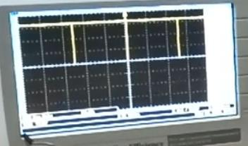
Results and Waveforms :
Duty cycle 50%:
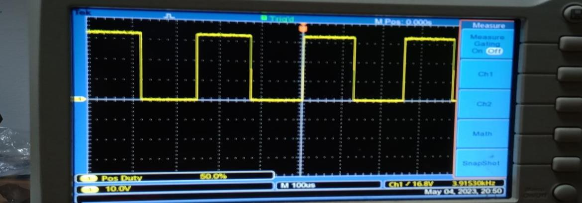
Duty cycle 100:
Conclusion:
Constant current and constant voltage method implemented using TIVA board to
charge battery model(RC).We have achieved constant 2.2 V at output of current
sensor in constant current method. And nearly 5V at output of L298N converter
in constant voltage method.
code: Code for regenerative breaking system
demo: Regenerative breaking for DC motor
Recent Comments