
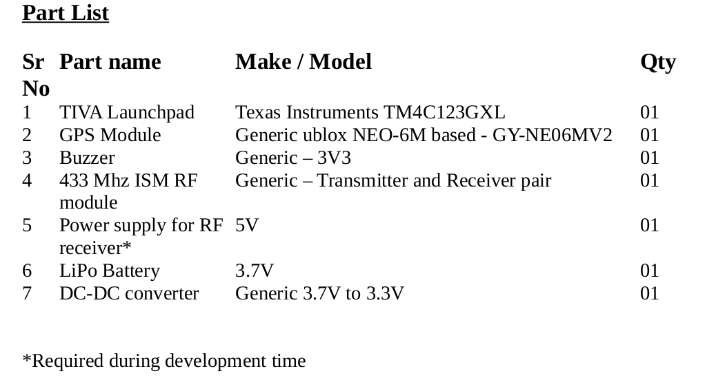
Motivation
With longer expectancy of life, their is a increase in number of senior citizens in cities. Parallely, the
families are becoming nuclear and less support is available for this ageing population. The senior
citizens are quite mobile due to good health and prefer continuing their earlier active lifestyle. But
due to age the family members are always worried when they step out of home. Their is a
increasing need to ensure safe pubic places [1] for ageing population. In this situation if a automatic
SOS device is available with these active senior citizens, that informs about the whereabouts and a
few vitals, it would relieve the stress associated with following a active lifestyle.
Introduction
In this project one such device is designed that solves the problem of unavailability of information
about emergency and location of the person in it. This device can be in any form factor – a watch or
a locket or even placed in waist belt. It has SOS button that can be pressed if the wearer senses a
emergency situation. It has a pulse sensor that can inform the pulse of the person in such SOS
situation. It has a buzzer that can inform the passerbyes and enable immediate help if required. The
device send the SOS situation, and pulse rate using 433 Mhz ISM transmission. If accidently
pressed the same button can be pressed again to cancel SOS.
Usage
The wearer steps out of home wearing this device. Receiver side is put to ON by the family
members. After a run or a walk if their is an emergency situation, SOS button will be pressed by
wearer. Immediately location data and pulse rate will be send to receiver side so that someone can
go and assist. Also the buzzer will sound and someone who is near can help and save the person.
Design
Interface SOS button and SOS acknowledge LED
Major functionality starts after pressing the SOS button. Pin PF0 is connected to SW2 in TIVA
board. This SW2 press is used to indicate SOS situation. On pressing SOS button the LED
connected to PF1 glows red. Sometimes a accidental press may happen. To cancel the same button
can be pressed to cancel the SOS state.
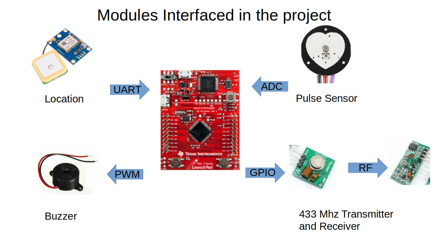
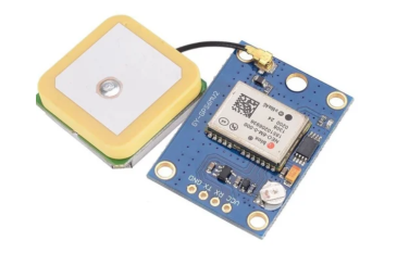
Interface GPS module
GPS module is connected to get the location information. This is connected to UART1 port using
pins PB0 as Rx and PB1 as TX. TX of the module is connected to RX of UART and RX of module
is connected to TX of UART. Instead of using interrupt based approach continuos read of GPS data
is done when in SOS mode. This will enable tracking of person even if he/she moves.
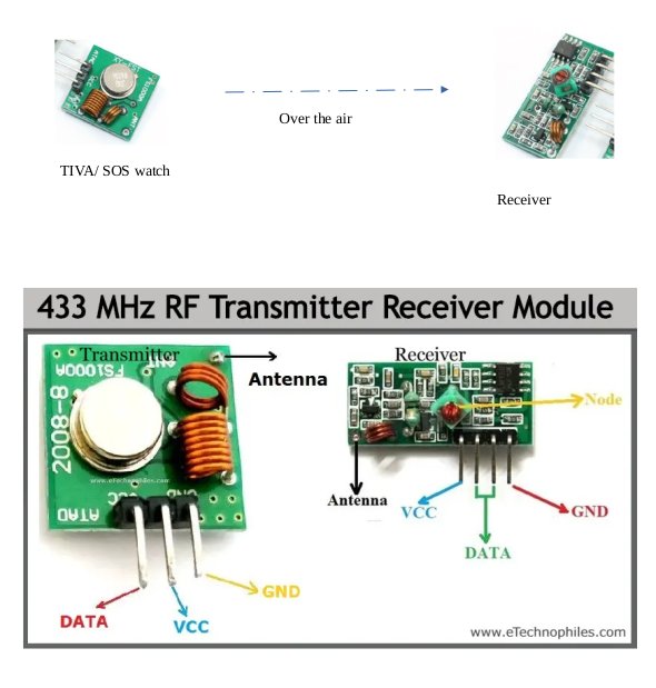
Interface RF module
RF modules are used to communicate the SOS condition over ISM band of 433 Mhz. The signal pin
of the transmitter module is connected to GPIO of PA2. On pressing the SOS button, this pin is set
high at a periodicity of 1 Hz using a SysTick Timer. On re-pressing and hence cancelling the SOS,
the pin is made low again, stopping the transmission.
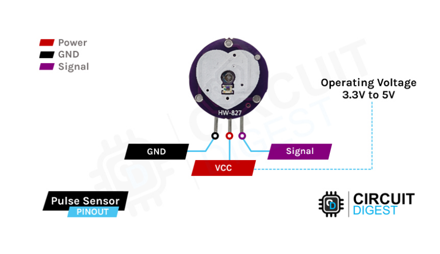
Interface Pulse sensor
Pulse sensor senses the pulse and if it becomes DC (a no pulse condition, which means an
emergency), it will send out a SOS signl out. This is a analog sensor and uses ADC Analog channel
2, ADC0 and connects to PE1 pin.
Interface Buzzer
Buzzer is interfaced to the PWM generator to generate a tone on pressing SOS button. It uses pin
PD0 with M1PWM0 (Motion Control Module 0 PWM 1).
Interface serial port (for connection to PC)
Serial port is used in this project to display the debug messages. It may also be used to program the
device by setting some parameters such –
Allowed GPS locations – this will help implement geo-fencing for the watch wearer
Pulse rate threashold for generation alerts
To connect to TIVA board, UART0 with pins PA0 as Rx, PA1 as TX was used. These are connected
via virtual com port enabling them to connect to USB port of PC.
Interrupt based mechanism is used allowing for interactivity without engaging the CPU time.
Receiver Side
On the receiver side a buzzer is connected to the signal pin. It buzzes with a frequency of 1 Hz of
receiving SOS signal.
Challenges encountered
1) The interfacing of RF modules was a challenge. To know if transmitter is working, receiver was
needed and vice-versa. Also, at 3.3V the RF power output was very low of transmitter. This limits
the range of use.
2) GPS fix was difficult in indoor locations
3) Heart rate detection was a challenge as it needs sophisticated algorithms that are difficult to run
in less memory. But detecting pulse was simpler and more useful
4) Some of the pins of UART are locked reducing the flexibility of usage of pins. This was
overcome by using another UART.
Further possibilities
1) Power saving measures – the data of SOS (SOS, Pulse/ No pulse) can be sent only in SOS
condition or peridocity can be defined based on thee battery condition (if low battery – transmit
once a hour, if battery is enough – transmit more often)
2) Geofencing can be done. GPS data of geo fence can be flashed and as soon as the wearer goes
out of that remote station can be alerted. This can be used by law-enforcement agencies apart from
the usual SOS application.
References
[1] Ageing and population shrinking: implications for sustainability in the urban century by Jarzebski et. Al, npj Urban Sustainability (2021) 1:1
code: Project_LED_blink_SOS_button_UART_GPS_RF_Buzzer_20675
demo: Location and Fitness tracker with emergency/SOS alert using ISM band
Recent Comments