
OBJECTIVE
The objective of the project was aimed at developing a Brushless DC Motor Control platform for electric vehicles using TM4C123GH6PM board.
BLDC MOTOR
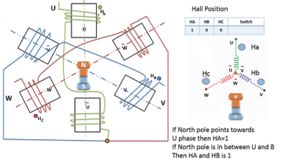
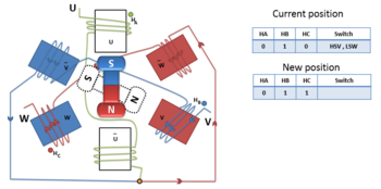
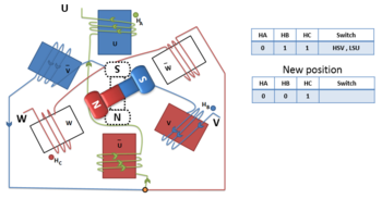
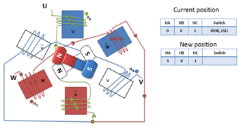
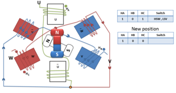
The brushless DC (BLDC) motor is equivalent to a permanent magnet DC motor except the commutation is done through an electronic means. The rotor consists of a permanent magnet and stator windings work in conjunction with the permanent magnet. Hall sensors are used which are embedded in motors to get the actual position of the rotor. The schematic of the BLDC motor showing the stator, rotor and Hall sensor value is shown in the figure below.
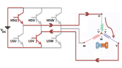
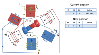
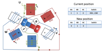
The advantages of the BLDC motor are that these motors offer a flat speed torque characteristics, output power to frame size ratio is high, dynamic response is fast and there is no presence of slip in the motor operation. For switching the BLDC motor, a 3 phase inverter is used. The three high side switches and three low side switches are switched on according to the hall sensors value. Consider U, V and W as the three phases at output of inverter with HSU, HSV, HSW and LSU, LSV, LSW being the high and low side switches respectively. The switching sequence for one complete rotation of BLDC motor is shown in the below figures.
IMPLEMENTATION BLOCK DIAGRAM
The BLDC motor controller was developed to be implemented on TM4C123GH6PM board. The block diagram considered for implementation is shown below. In this study, the main focus was on the control for the vehicle and the charging of the DC bus is not discussed.
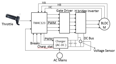
Hall sensors used are embedded in the BLDC motor. These sensors provide the rotor position. The voltage sensors are required for measuring the battery voltage. A throttle which is basically a potentiometer is used to provide the speed reference to the BLDC motor.
PWM Module
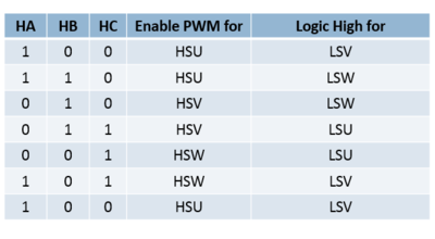
The PMW module of the board is configured to operate in symmetric and independent mode. 3 PWM signals are required to switch the high side switches of the inverter used. Since, in the switching sequence, at any instant of time no two switches are on, hence PWM can only be applied to high side switches. The low side switches can provide high output whenever required through any GPIO output port. Thus, there is no requirement of providing any deadtime for the PWM pulses. PWM is operated in unison with the hall sensors. The status of the hall sensors are taken as input through GPIO ports. The corresponding PWM to the input status of hall sensors is enabled at that instant. The table below shows the PWM and logic high requirement of the switches based on the hall sensor values.
ADC Module
ADC is used to interface the continous analog signal input with the digital domain. The throttle input is provided through the ADC of board. The board contains a 12 bit SAR ADC with maximum sampling rate as 1 MSPS. The voltage range is 0 – 3.3 V. ADC is operated in single ended mode to obtain the throttle input value with respect to ground.
Firmware Design
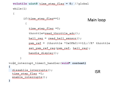
The BLDC motor drive is operated at a frequency of 4 kHz. So the PWM period register value should be set to 0x0FA. For a 100% duty cycle, the reference value should be equal to the PWM period register. For speed reference, ADC converts the throttle input to a digital value. In order to run the motor at rated speed, it is necessary to apply 100% PWM. Hence, a factor ‘k is calculated such that 0xFFF*k = 0x0FA. The value of ‘k’ is used to provide the speed reference. The breaks for the motor are configured as interrupts and whenever break is applied the PWM is stopped so that the motor decelerates. The pseudo code for the desired operation is shown in the figure below.
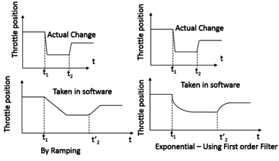
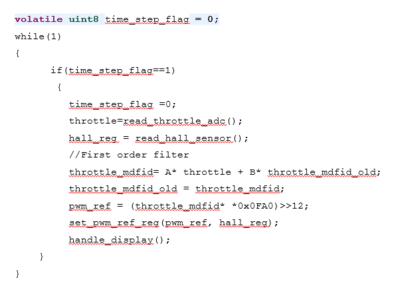
Practical Issue – Jerking
Whenever the throttle input change, sudden acceleration or deceleration causes Jerking and this needs to be avoided. So, while changing the PWM reference value according to the throttle input, the change in the reference value can be adopted by ramping the change or exponential change of the value. The change of reference by exponential way is preferred and this can be achieved through passing the reference value through a digital low pass filter equation.
The pseudo code to achieve the desired operation is shown in the figure below.
Hardware Requirement
The PWM outputs of the board cannot turn on the power switches of the inverter. A gate driver circuit is necessary for firing of power switches. For the high side switches, a separate isolation will be provided while for the low side switches, common ground can be used. Considering the requirement, IR2110 a boot strap gate driver can be adopted for implementation. The rating of motor is considered as 250 W. and the DC bus voltage for inverter is 24 V. A power MOSFET – IRFP 250N (VDS= 200 V, IDS= 30 A) is suitable for implementation.
CONCLUSIONS
BLDC motors are very efficient for electric vehicle applications. The requirement of a permanent magnet in a BLDC motor is of concern as availability of the magnet is very uncertain. As a result, researchers are looking for use of other motors such as SRM. However, in case of SRM commutation and control is bit complex. However, the advantage is the same control architecture as explained for the BLDC motor can be adopted for any other motor used for electric vehicle application.
References
1. Jian Zhao, Yangwei Yu, “Brushless DC Motor Fundamentals”, Application Note AN047, Monolithic Power, Rev. 1.0, July 2014.
2. Hardware Design Considerations for an Electric Bicycle Using a BLDC Motor, Application Note SLVA642 by Texas Instruments.
3. Brushless DC Motor Made Easy ,AN857 Microchip.
4. Md. Fahim Bhuiyan, Mohammad Rejwan Uddin, Zaima Tasneem, Mahady Hasan and Khosru M Salim, “Design, Code Generation and Simulation of a BLDC Motor Controller using PIC Microcontroller”, Proceedings of IEEE International Conference on Recent Innovations in Electrical, Electronics & Communication Engineering, 2018.
5. Hongmei Yang, Xin Yu, Hua Guo and Xinglin Zhang, “Design of Brushless DC Motor Control System based on ARM”, Advanced Material Research, 2012.
Recent Comments