
Abstract
We propose a system design for a Point-to-Pont Free Space Optical Communication system for Low Earth Orbit satellite to Geostationary Orbit satellite. This study project was aimed at designing a Datalink/Transport layer protocol for the high-speed optical link between an imaging LEO and a relaying GEO satellites. ARM Cortex M3 based microcontroller will be considered for implementing the protocols and the state machines, while assumptions will be made for interfacing units and physical layer elements.
Introduction
High-resolution imaging LEO satellites generate vast amounts of data but have a very small window for the downlink of the data. This proves restrictive for mission planning, as only a small amount of imaging can be planned on a given day. Typically, a satellite gets around 10-15 minutes per ground station. A solution to this problem is a Geostationary satellite that acts as a relay between orbiting LEO satellite and the ground station (GND), which it continuously faces. The high-speed data can be transmitted from LEO to GEO in optical mode, while the data transfer between GEO and the GND can be slower, traditional RF link.
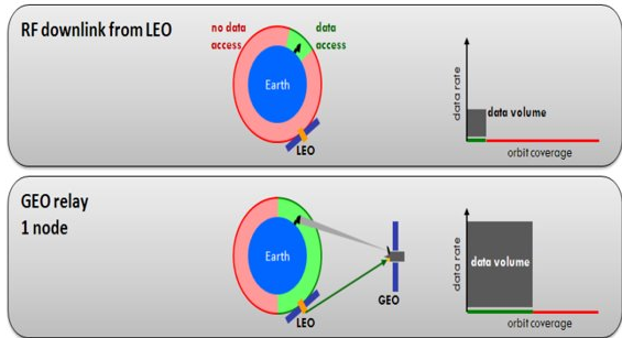
Other advantages of Optical link is that there is virtually no interference, which is desirable from both data integrity and security point of view. This is because it is highly directive and has low spatial spread. The high directivity means that there needs to be an active tracking mechanism to maintain lock with the beam. Therefore we also have to implement a motor based tracking system for the telescopes on LEO and GEO.
System Specifications
We will take the case of an imaging satellite at 400 km orbit and a GEO at the usual 36000 km orbit. The data channel is optical, one-way between LEO and GEO while the control or management channel is RF-based. The figure below illustrates these parameters.
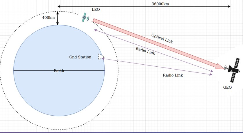
Some detailed specifications and calculation considered here: • Orbital Period of LEO: ~100 min
• Total no. of orbits: ~14.4
• No. Of orbits in GEO visible zone: ~6-7
• Average amount of time available for data transfer: ~247 min, as opposed to ~50 min due to multiple ground stations
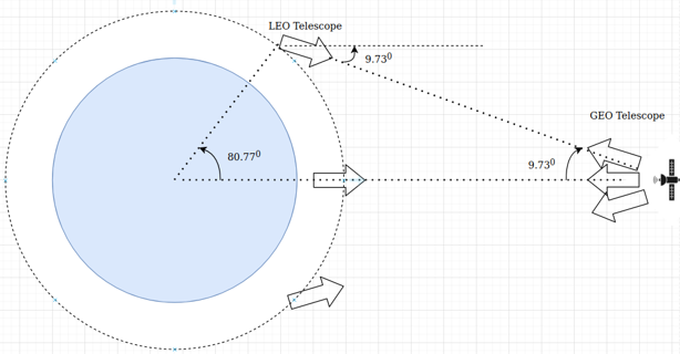
• Time available in Nadir (Coplanar) configuration: 45 min
• Max total angle rotation (Coplanar config): ~19 deg
• Amount of data generated: ~4Tb
Tracking
To lock into the beam before communication, we use optical components like Beam Splitter to split the incoming beam into two beams: one goes into an area array sensor and forms a spot for tracking and other goes to a fibre-optic coupler where it subsequently goes to the optical data processing unit. The beam is imaged as a spot on the sensor and the goal is to bring it to the centre so that the other half of the split beam is perfectly coupled with the fibre-optic. First stage to go through is acquisition, or ACQ. The Az and El motors of GEO try to bring the spot to a bounding box. Then the TRK mode takes over whence the motor is controlled to make sure that the spot stays in the box during the data transfer. The LEO motors follow an angular profile per orbit to make sure the beam is incident on GEO. Following image illustrates tracking process. (L) shows a typical AZ-EL motor arrangement, (M) shows the optics schematic and (R) shows the spot formation upon sensor and the ACQ and TRK process.
![]()
As per detailed calculation, tracking is seen to be a slower process than communication, with former nearly a thousand times slower than the latter. Therefore, all tracking activities can take place in an ISR while the communication state machine can take place in the main().
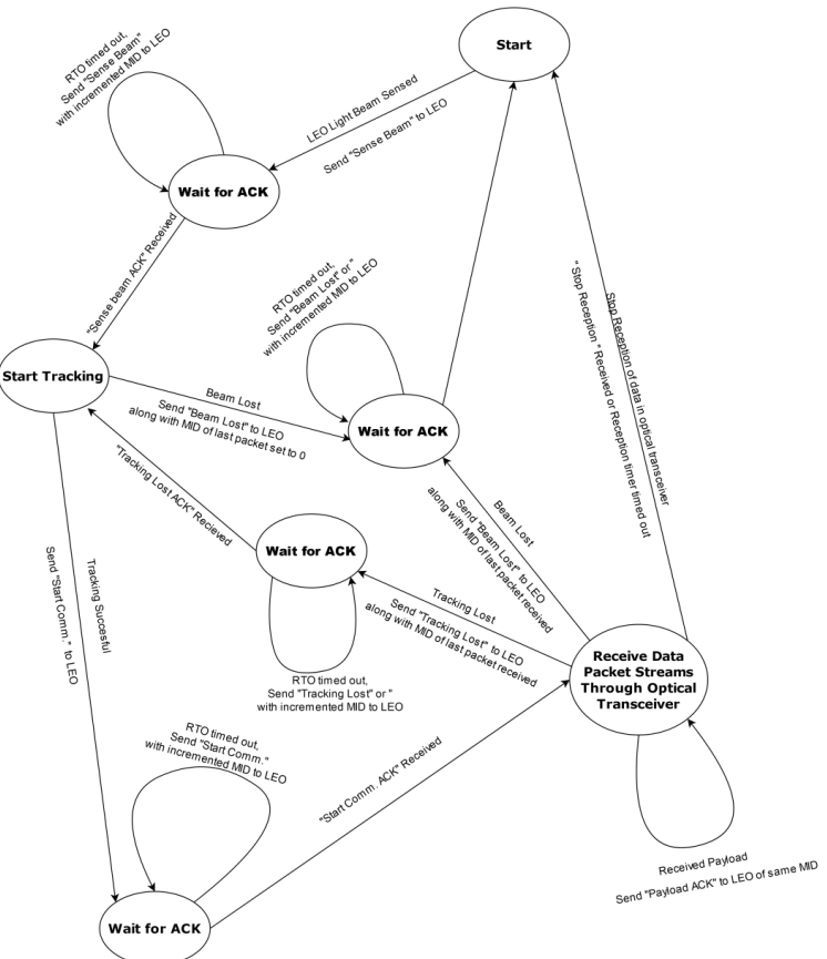
Communication
The communication design involves the design of packet structure for data and control packets and manages the state machine to ensure a reliable communication through the optical link, which is a high bandwidth, high-throughput link. The ACK can be through much less directive but slower RF link. The following diagram gives GEO side communication State Machine:
The following state machine is for LEO terminal:

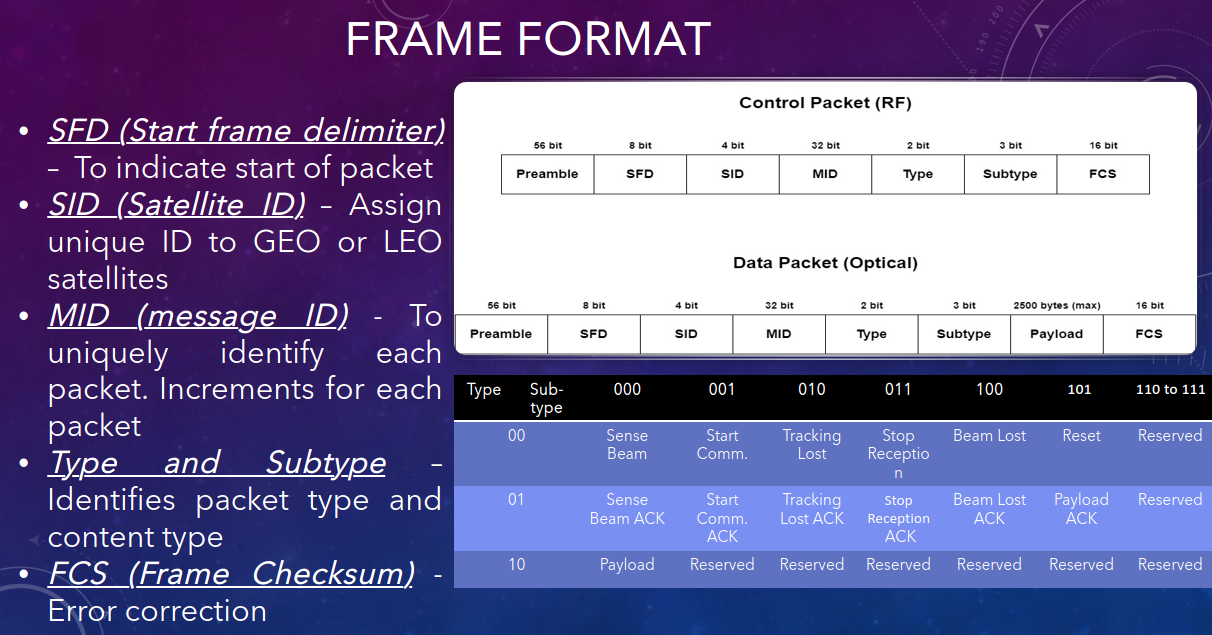
The frame format is given below. It can be noted that provision has been made for multiple LEO satellites to upload to same GEO satellite. Many LEO missions involve multiple similar satellites collecting data, and a mission design where one LEO satellite transmits while others are in the non-visible zone for GEO can ensure maximum efficiency. Thus the entire system design is scalable.
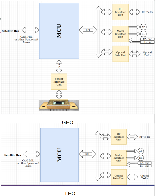
MCU Interface
The following figure shows the MCU interface for both LEO and GEO terminals. Possible candidates for MCU are Tiva TM4C129XNCZAD andTM4C123GH6PM. Motor, Motor Encoders, Image Sensors and Optical Data Chain are all interfaced using an interface unit, which we assume will abstract the component or part-specific details from the processing and control unit inside the MCU. This makes our design very portable. MIU converts motor Az-El commands to the required drive for motor and appropriately formats Az and El encoders and relays it to MCU. Sensor unit reads the data from the sensor and computes spot centroid. ODU interfaces with the data-chain and extracts meta-data from incoming packets for the FSM inside MCU. RF link interfaces with the RF unit for ACK communication and satellite bus interface with the main bus of the satellite.
References
• Benzi, Edoardo, et al. “Optical Inter-Satellite Communication: the Alphasat and Sentinel-1Ain-orbit experience.” 14th International Conference on Space Operations. 2016.
• Dreisewerd, D. W., et al. “A high data rate LEO to GEO optical crosslink design.” MILCOM 92 Conference Record. IEEE, 1992
• Edwards, Bernard L., et al. “An overview of NASA’s latest efforts in optical communications.” 2015 IEEE International Conference on Space Optical Systems and Applications (ICSOS). IEEE, 2015.
• Ruilope, Ricardo Picatoste. “Modelling and control of stepper motors for high accuracy positioning systems used in radioactive environments.” дис./Ricardo Picatoste Ruilope (2014)
• Datasheets and Product Information
Recent Comments