
Main Objective
The objective of the project is to design an ball pitching machine with configurable settings. User should be able to launch the balls automatically at different adjustable speeds.
Design aspects
Block Diagram
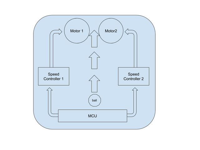
Components
- BLDC motors(Turnigy Multistar 3525-750Kv 14Pole Multi-Rotor Outrunner) X 2
- ESC motor drivers(HobbyKing 70A ESC 4A UBEC) X 2
- Rubber wheels X 2
- Frame mount with slider arrangement
- Controller (Tiva C series Launchpad)+ ESP12 WiFI module
- Motor Fixing nuts, bolts and Miscellaneous (wires, snugs, sleeves)
- 3S 5200mAh battery
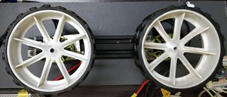
Mechanical design
Machine consists of two wheels with rubber tires, each rotating by its own electric motor. These are fixed on a frame such that the wheels are in the same plane with a sliding arrangement, about 8 cm apart. The slider block can slide over the base by means of a screw and nut mechanism, which is attached at each end of the base motor for accommodating balls of different diameters. The whole assembly is fixed on a reference frame so that the plane of the wheels is roughly at the height that a typical bowler would release the ball.
Controller Design
A controller allows variation of the speed of each wheel, allowing the machine to achieve variation in speed and movement in air bowling can also be achieved. Both the motors rotating in same speed get the ball pitched straight.
- Variations in speeds result in slower and faster ball delivery
- By setting the speeds one of the motors different we get the movement of the ball either side depending on which motor is slower.
Electrical Design
Motors
Turnigy 750Kv Brushless DC motors are used in this project, Also kV means how many rpm motor has for each volt i.e for 3S battery (12.64V) the max rpm at full battery is 9480.
ESC
Hobby kit 70A Electronic Speed Control modules are used, By Adjusting Duty Cycle or Switching frequency of Transistors, the speed of the motor is changed. The BLDC motros speed is varied by adjusting the timing of the pulses of the current delivered to the motors.
So, for a PWM, the writing period to be as fast as you can. Normal ESCs have refresh rates from 50Hz to about 400Hz. At 500 Hz you would already have a problem because the period would be the same as the longest PWM value. To produce the period duration from 1000us to 2000us the PWM frequency should be 400hz.
Electronic Design
MCU
Tiva C Series Launchpad is used to provide the pulses to the ESCs using PWM. And potentiometer is used to provide manual throttle control. and ESP12 board is used to provide WiFi, ESP and MCU are connected via UART.
PB6 pin is used as Analog input for POT.
Code snippet for reading POT
SysCtlPeripheralEnable(SYSCTL_PERIPH_ADC0); SysCtlPeripheralEnable(SYSCTL_PERIPH_GPIOB); GPIOPinTypeADC(GPIO_PORTB_BASE, GPIO_PIN_6); ADCSequenceEnable(ADC0_BASE, 0); ADCSequenceDataGet(ADC0_BASE, 0, ui32ADC0Value);
now the range of the values is converted to the range of pulse period of the PWM signal. Similar map function from ardiuno library is used.
float value = (x – in_min) * (out_max – out_min) / (in_max – in_min) + out_min; // From Arduino source code: https://github.com/arduino/Arduino/blob/ide-1.5.x/hardware/arduino/avr/cores/arduino/WMath.cpp return value;
PB5, PB4 are used to generate PWM signals for Motor control.
Code Snipnet for setting up the PWM
   SysCtlPeripheralEnable(SYSCTL_PERIPH_PWM0); // Enable PWM peripheral
   SysCtlDelay(5); // Insert a few cycles after enabling the peripheral to allow the clock to be fully activated
   SysCtlPeripheralEnable(SYSCTL_PERIPH_GPIOB); // Enable GPIOB peripheral
   SysCtlDelay(5); // Insert a few cycles after enabling the peripheral to allow the clock to be fully activated
   // Use alternate function
   GPIOPinConfigure(GPIO_PB5_M0PWM3);
   GPIOPinConfigure(GPIO_PB4_M0PWM2);
GPIOPinTypePWM(GPIO_PORTB_BASE, GPIO_PIN_5 | GPIO_PIN_4); // Use pin with PWM peripheral
   // Configure the PWM generator for count down mode with immediate updates to the parameters
   PWMGenConfigure(PWM0_BASE, PWM_GEN_0, PWM_GEN_MODE_DOWN | PWM_GEN_MODE_NO_SYNC);
   PWMGenConfigure(PWM0_BASE, PWM_GEN_1, PWM_GEN_MODE_DOWN | PWM_GEN_MODE_NO_SYNC);
   PWMGenPeriodSet(PWM0_BASE, PWM_GEN_0, period); // Set the period
   PWMGenPeriodSet(PWM0_BASE, PWM_GEN_1, period);
   // Start the timers in generator 0 and 1
   PWMGenEnable(PWM0_BASE, PWM_GEN_0);
   PWMGenEnable(PWM0_BASE, PWM_GEN_1);
   // Enable the outputs
   PWMOutputState(PWM0_BASE,PWM_OUT_2_BIT |  PWM_OUT_3_BIT, true);
For ESP standard Ardiuno IDE is used to program using ESP8266WebServer library. You can look at source code for ESP and Tiva Board here :
https://github.com/srikrishna3118/ball_pitching_machine.
Recent Comments