
Motivation
An important function of a well-designed battery charger is to charge the battery at an optimum rate, plus terminate the charging at the right time. Overcharging the battery stresses the chemicals inside the battery by forcing them recombine faster than they can, whereas frequent undercharging may result in problems such as sulfation. Overcharging as well as undercharging reduce battery life.
The aim of this project is to design a battery charger which could charge the battery with an optimum charge profile.
Some essential battery jargon
What is C-rate?
It refers to the rate at which the battery capacity is built-up or given up. For instance, if there is a 10 Ah battery, then a C-rate of ‘0.1 C’ (or C/10) denotes charging / discharging the battery for a duration of 10 hours. This corresponds to an average current of 1 A.
A charging C-rate of 0.1 C for a 10 Ah battery (1 A) is taken as a reference for this work. Hence, the power converter is designed to handle a maximum current of 1 A plus around 10 percent ripple.
Charging Batteries: The CCCV Scheme
CCCV refers to Constant Current Constant Voltage charging scheme. The method is used for charging Li-ion and Lead acid batteries. The constant current is the maximum safe charging current suggested by the manufacturer. The scheme switches the charging from Constant Current to Constant Voltage mode after a certain voltage is reached. This serves two purposes – first, the constant voltage mode avoids overcharge of the battery. Second, the charging rate is enhanced. The constant current portion of the charging is presented here.
Emulating a battery using rheostat (in constant current mode)
Let us say we want to design a charger for a constant current mode of 1 A current. If this current is passed through a resistor of (say) 10 Ω, the resulting voltage drop would be 10 V. While if the same current is passed through a 15 Ω resistor, the drop is 15 V. Hence, changing the rheostat setting from 10 ohms to 15 ohms (while current is held at 1 A) emulates a battery charging from 10 V to 15 V. The microcontroller has two jobs:
- Provide PWM pulses with enough duty cycle to keep the current constant at 1 A while the rheostat setting changes,
- Cut-off charging (or PWM pulses) when the terminal voltage reaches 15 V (equivalent to battery being charged up to the limit of constant current mode, and ready to be switched over to constant voltage mode).
Block Diagram
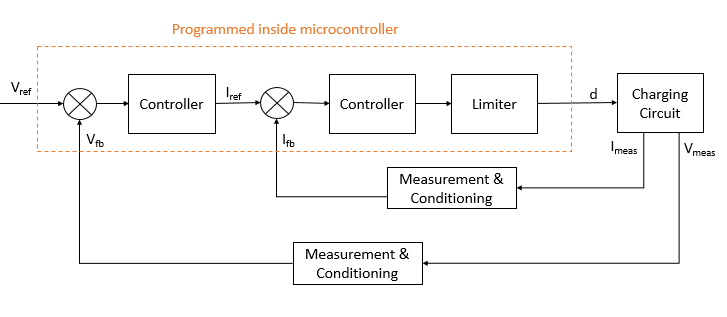
A top-level block diagram of the implementation is as follows. The controller can be a PI controller. The limiter limits the value of duty ratio to a range for which the power converter of charging circuit is designed. In essence, the system keeps the current value at a reference level. The reference current in turn is set by the voltage level dynamically.
Design and Implementation
Components
- MOSFETs – IRFZ44n
- Diode (fast recovery) – BY399
- Capacitor – 10 μF, 63 V
- Current sense resistor – 0.22 Ω
- Rheostat – 50 Ω, 5 A
- Inductor – 1.6 mH, 1.1 A (peak-current rating)
- Resistors : 47 kΩ (4), 4.7 kΩ (2), 8.2 kΩ (2), 100 Ω (2), 2.7 kΩ (3), 5.6 kΩ, 560 Ω, 1.5 kΩ, 3.3 kΩ (2)
- Zener diodes – 3.3 V (2)
- PNP Transistors – 2N2905A (2)
- NPN Transistors – 2N3019 (2)
- Operational Amplifier – LM324
Circuit Schematic
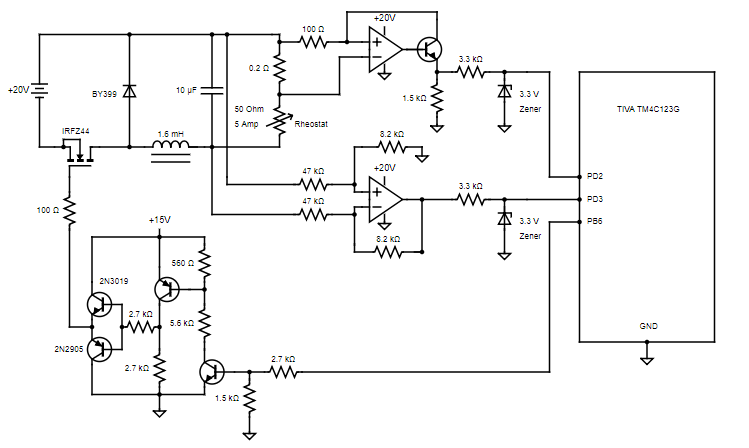
• Pin PB6 is the PWM output pin. PD2 and PD3 are input pins for the ADC.
• For current measurement, the supply voltage for operational amplifier needs to be little more than 20 V if measurements are done on ‘high side’. If ‘low side’ current measurement is done, a high supply voltage isn’t required.
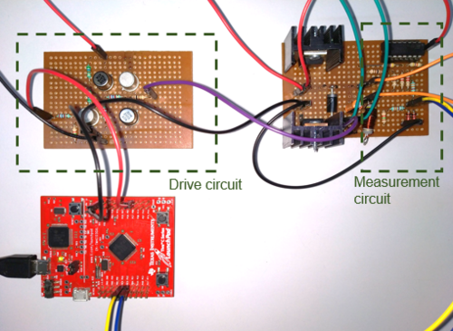
Gallery
The setup was as follows:
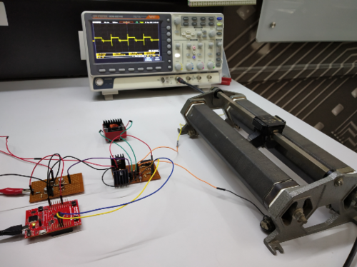
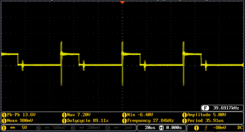
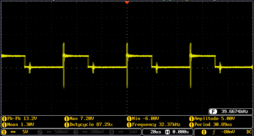
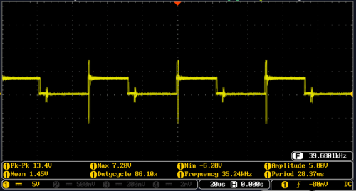
The below waveforms show the increase in PWM to maintain constant current as the rheostat setting is increased.
A word of caution
While interfacing microcontroller with power circuits, it is a good idea to use a USB-port isolator for protecting PC / microcontroller (against overvoltages, ESD shocks, ground loop interference etc). Otherwise, the whole setup will have the same ground point. Any issue at one location will propagate to the other locations, and there will be a risk of damage.
Resources
Find the implementation code here: Current Controlled Battery Charging
Useful datasheets:
Recent Comments