
Introduction
This project is aimed at developing a gateway between CAN bus and I2C bus networks. CAN is a widely used protocol in automobile systems, production machinery, factory and industrial automation. The increase in the amount of sensors, actuators and controllers that need to be connected to the system has raised the requirement of micro-controllers with multiple inbuilt CAN peripherals. Thus, the overall system cost naturally increases. Also, as CAN works on differential signaling, the current flowing in each signal line is equal but opposite in direction, resulting in a field-canceling effect that is a key to low noise emissions. This allows a bus length of 40 m using twisted pair cables. When many of the nodes are very close to each other, such elaborate measures for low noise coupling may not be needed and thus the cost of additional CAN controllers can be brought down. A local I2C bus can be set up for this purpose.
Objective
To develop a gateway is provided between the CAN and I2C bus that can:
• Provide data sent on the CAN bus to the I2C bus
• Send periodic updates from I2C devices to the CAN bus
• Respond to data requests on the CAN bus, fetch data from the concerned I2C device and send it on the CAN bus
Components Required
1. 2 Tiva Launchpad
2. 2 MCP2551 Transceivers
3. 2 120 ohm resistors
4. Kvaser USBScan Professional
Schematic
The Schematic of the proposed system is as follows:
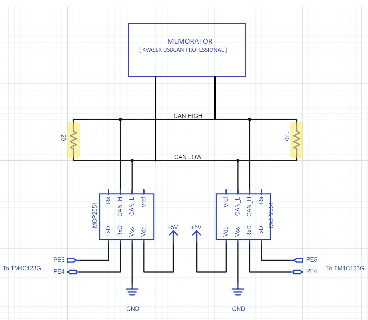
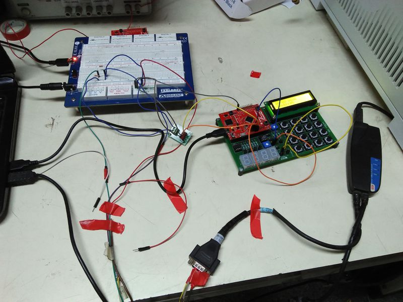
Image shows the Kvaser Can Peripheral on the right. The transceiver is to left of Launchpad. Terminating Resistors on the breadboard show the CAN Bus. Tiva Launchpad displays CAN Bus data over UART and Kvaser CAN Peripheral displays data on the PC screen over USB (SocketCAN).
Different Modes of CAN Implementation using Tiva Launchpad
Mode 1 (Rx) : In this mode, Tiva Launchpad works as a receiver on the CAN Bus and receives all the messages on the CAN Bus and log it.
Mode 2 (TX) : In this mode, Tiva Launchpad works as a transmitter on the CAN Bus and transmits messages on the CAN Bus with a single or multiple IDs and hence compete on CAN Bus according to message identifier. Lower the message identifier, higher the priority of the message.
Mode 3 (RTR Query) : In this mode, Tiva Launchpad sends a remote frame on the CAN Bus with no data and message identifier being the identifier of the node which it is requesting to transmit.
Mode 4 (RTR Response) : In this mode, if Tiva Launchpad receives a remote frame on the CAN Bus with no data and message identifier being its message identifier, then it responds with the appropriate data frame.
In our project, we have explored all the 4 modes on Tiva Launchpad. Commands are to be entered in UART shell.
Mode 1: Here, Tiva Launchpad acts as CAN Bus sniffer which just continuously listens to the messages on the network which are randomly generated by Kvaser Memorator.
Mode 2: Here, Tiva Launchpad generates messages (date and time) continuously and Kvasaer Memorator listens to the messages on the network.
Mode 3 : Here, Tiva launchpad sends a remote frame on the network with the identifier either being the identifier of Memorator or other Tiva Launchpad on the network. In case, it is the identifier of the memorator, it just receives the remote request because it is not programmed to respond. When the identifier matches the identifier of the other CAN node ( Tiva Launchpad on the network, it responds with current date and time by requesting RTC(Real-time clock) on it by I2C communication.
Mode 4: Here, Tiva launchpad responds with date and time on being sent remote frame by Kvaser Memorator or other Tiva launchpad.
So, a remote I2C peripheral can be accessed over CAN Bus.
Source Code
Code for the project can be found at https://github.com/gsomani/can_tiva_launchpad
README.md file provides all the documentation required to use this project folders under different modes and also about installing can-utils for controlling and receiving network traffic on can0.
Screenshots of UART Terminal (data log by Tiva Launchpad on CAN Bus) and SocketCAN interface(can0) on terminal
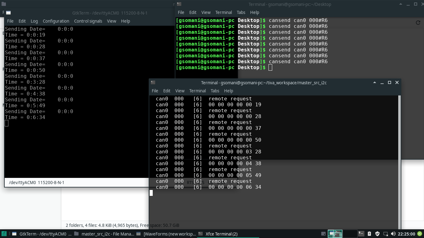
RTR sent by can0 ( Kvaser USBScan Professional) is answered by Tiva Launchpad by giving current date and time by querying I2C peripheral RTC. Image on the left shows data sent by Tiva Launchpad on request by can0. Image on the right shows data received by can0.
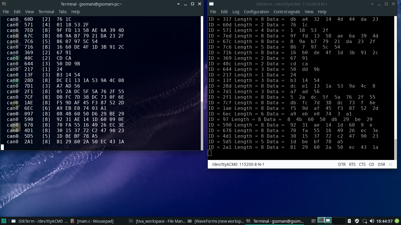
can0 generates random id and data using cangen. Data received by TIVA CAN Launchpad is displayed on UART Terminal. candump shows data sent by can0. Image on the right shows data received by Tiva Launchpad. Image on the left shows data sent by can0.On left, Data sent by launchapd is shown(ID is incremented along with data being sent). On right, data recived by can0 is shown.
Future Work
1. All the functionalities ( RX, TX, RTR) can be integrated into one program and Tiva Launchpad can be made into CAN Controller which logs data over UART.Different commands for different actions can be developed.
2. Kvaser CAN peripheral can be made to act in a custom manner by programming traffic control using Socket CAN API.
3. Tiva Launchpad along MCP2551 can be made compatible with Socket CAN so that Socket CAN works out of the box for it.
Further updates will be coming on Github repository of this project.
References
1. TivaWare_Peripheral_Driver_Library__Users_Guide
2. https://github.com/linux-can/can-utils
3. Kvaser USBSCan Professional Uer Guide
Recent Comments