
Project Overview
The project proposes implementation of a low cost navigation system based on the commercially available IMU (Inertial Measurement Unit) module and GPS (Global positioning system) module. Both the modules will be simultaneously calculating the location. For specific strategic applications where the GPS signal may get cut off, IMU module will calculate the position thereafter with a certain integrating error of the dead reckoning system. The error correction will be done once a valid data is obtained from the GPS signal.
Resources
Tiva C series microcontroller : TM4C123GH6PM
PIC microcontroller : PIC18F4550
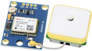
GPS receiver Neo-06 module
GPS Neo-06 module
| Name | Example | Units | Description |
|---|---|---|---|
| Message ID | $GPGGA | GGA Protocol Header | |
| UTC Time | 184241.000 | hhmmss.sss | |
| Latitude | 1829.9639 | ddmm.mmmm | |
| N/S Indicator | N | N=North, S=South | |
| Longitude | 07347.6174 | dddmm.mmmm | |
| E/W Indicator | E | E=East, W=West | |
| Position Fix Indicator | 1 | Fix GPS SPS mode | |
| Satellites Used | 05 | Range 0 to 12 | |
| HDOP | 2.1 | Horizontal Dilution of Precision | |
| MSL Altitude | 607.1 | Meters | Mean Sea Level |
| Units | M | Meters | |
| Geoid Separation | 64.7 | Meters | |
| Units | M | Meters | |
| Age of Diff. Corr. | – | Null field if DGPS is not used | |
| Diff. Ref Station ID | 0000 | ||
| Checksum | *7C | ||
| Carriage return Line Feed | <CR><LF> | End of message transmission |
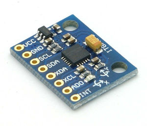
MPU 6050 module
MPU 6050 module
Gyroscope
The triple-axis MEMS gyroscope in the MPU-60X0 includes a wide range of features: Digital-output X-, Y-, and Z-Axis angular rate sensors (gyroscopes) with a user-programmable fullscale range of ±250, ±500, ±1000, and ±2000°/sec. External sync signal connected to the FSYNC pin supports image, video and GPS synchronization. Integrated 16-bit ADC’s enable simultaneous sampling of gyroscope data. Enhanced bias and sensitivity temperature stability reduces the need for user calibration. It has an improved low-frequency noise performance and a digitally-programmable low-pass filter.
  Operating parameters:
  Gyroscope operating current: 3.6mA
  Standby current: 5µA
Accelerometer
Digital-output triple-axis accelerometer with a programmable full scale range of ±2g, ±4g, ±8g and ±16g. Integrated 16-bit ADCs enable simultaneous sampling of accelerometers while requiring no external multiplexer. Orientation detection and signaling. User-programmable interrupts and High-G interrupt.
  Operating parameters:
  Accelerometer normal operating current: 500µA
  Low power accelerometer mode current: 10µA at 1.25Hz, 20µA at 5Hz, 60µA at 20Hz, 110µA at 40Hz
  Configuration registers:
  Device_Address = 0x68
  PWR_MGMT_1   = 0x6B
  SMPLRT_DIV   = 0x19
  CONFIG       = 0x1A
  GYRO_CONFIG  = 0x1B
  INT_ENABLE   = 0x38
  ACCEL_X = 0x3B
  ACCEL_Y = 0x3D
  ACCEL_Z = 0x3F
  GYRO_X  = 0x43
  GYRO_Y  = 0x45
  GYRO_Z  = 0x47
Block Diagram
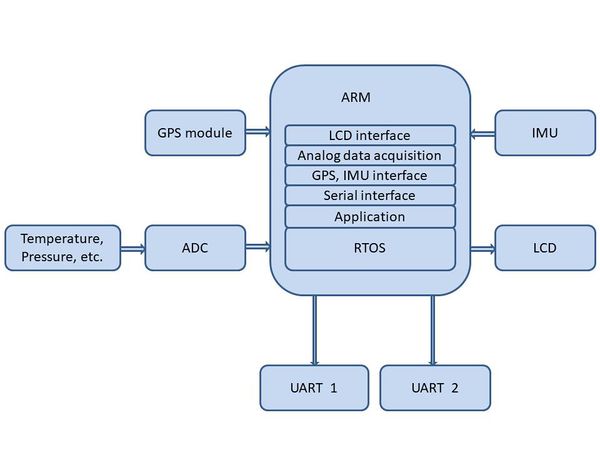
Functional block diagram
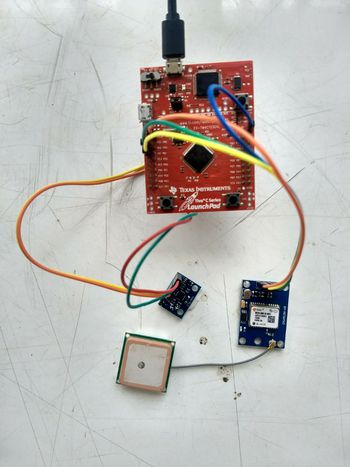
TM4C123GH6PM test setup
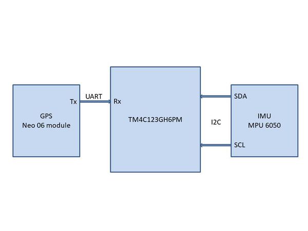
Interfaces diagram
PIC18F4550 test setup
(RTOS is not implemented as a part of this project)
Algorithm
1.Initialize I2C communication.
2.Initialize the baud rate.
3.Initialize the MPU6050 IMU.
4.Read the data Ax, Ay, Az, Gx, Gy and Gz (16 bits each) which is in Q15 format (1.xxxxx).
5.Calculate the displacements along all three axes by integrating Ax,Ay and Az twice with respect to time, thus find the effective displacement magnitude.
6.The direction of displacement is found out by integrating the gyroscope values with respect to time.
5.Thus, compute navigation.
6.Perform serial transmission.
7.Correct the IMU data periodically to remove the error due to integration of noise in IMU.
8.The GPS data is extracted through UART.
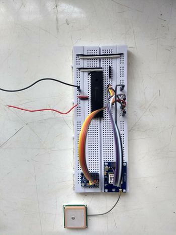
Implementation
The system has been implemented on both PIC18F4550 and TM4C123GH6PM. We used TI-RSLK Texas instruments Robotics System Learning kit for evaluation. This kit is programmed for moving in different directions.The on-board navigation system will compute the position each second periodically and sends back to the user. User can press “Update GPS coordinate” for the updating the INS data with GPS.
Source codes
The following link has the codes for implementation of this project in both TM4C123GH6PM and PIC18F4550.
https://github.com/akshaym1995/Embedded-project
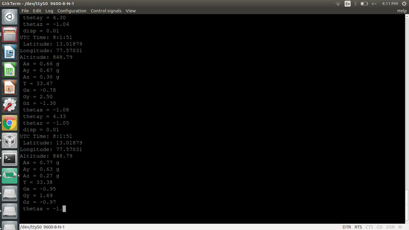
Experimental Results
The output window shows the GPS coordinates and also the displacement and orientation using IMU.
Future Scope and Applications
1. Real time scheduling of data acquisition, transmission and processing can be implemented efficiently using RTOS.
2. Implementation of Kalman filter will remove the integrating error of dead reckoning system.
3. This system can be used for strategic space applications, missiles, etc.
Recent Comments