
Contents
1 Problem Statement
2 Components
3 Functional Description
4 Physics Involved
5 Major Contributions
5.1 Ultrasonic Sensor
5.2 Line Camera Freescale
6 Conclusion
7 Reference code
8 References
9 Team Members
Problem Statment
The project aims at stabilizing a 2 wheel Robot. The robot should be stable against the minor external disturbances and should be able to maintain its balance. Once the
robot is balanced, it will take up the line following task using a line camera(Freescale). Further the ultrasonic sensor has also been interfaced to detect obstacles while
moving. All task are managed by RTOS based on their priority. Balancing is the most critical task in this project and thus it has the highest priority.
Components Required
Structure/Chasis of Car                              - 1
DC-Motor (Preferably 5A motor)                       - 2
Battery (7.2V, 1A)                                   - 1
Tiva launch pad board (for TM4C123GXL)               - 1
Sensor hub Booster pack for launch pad               - 1
Motor driver L298 Board or IC (Board is preferred)   - 1
Wheels for Car                                       - 2
Switches (for ON/OFF) (We used SPDT swich)           - 1
Freescale Line Camera                                - 1
HCSR04 Ultrasonic Sensor                             - 1
Design schematic that is followed
Functional Description
Self balancing structures are ideal example to prove the extend of applicability of embedded systems, ruggedness of control systems
and an example to handle real-time systems. From the embedded context, these type of projects are helpful in providing the designer a much
better insight about RTOS (real time operating systems), FPU (Floating point units) and control system error correcting and balancing techniques.
     Here in this project we are targeting to self balance a two wheel robot which is inherently unstable(Inverted pendulum). This is a real time
system based on RTOS and manages various tasks based on priority. Here we develop motor driving electronics(Hardware), PID control, filtering
techniques and RTOS(Software) as the part of the project.Different sensors such as Line camera and Ultrasonic sensors and a sensor hub are used to aid
the bot to balance efficiently and to avoid obstacles while moving.
Physics Involved
Here the force which makes the system to unstable is the rotating torque in the direction of C.G (centre of gravity) shift. To compensate this we move the wheels in a direction which counter balance the torque from C.G. i.e the net torque makes the system stable at the desired angle.
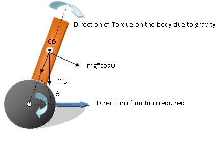
Inverted Pendullum
How does control system work???
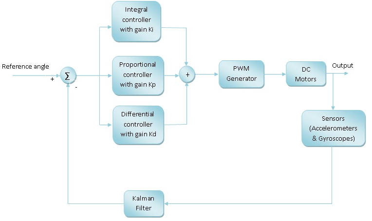
This is how we implemented Control System

Major Contributions:
This project was started by our seniors and we have taken their work and added Ultrasonic
sensor interfacing. Also as the robot mechanical design was not proper the robot was not
able to balance. The CG of the bot was not at a proper position for efficient balance.
So our first task was to improve the mechanical design. We referred various papers and
tried to improve upon the design. We came up with a 3 layer design which improved the
stability of the system.
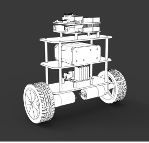
New structure of robot
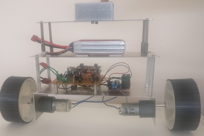
During the course of project we have realized the earlier battery was not able to provide the required current to the motor. So we have used a rechargeable 2200 mAH High Magnification Lithium Polymer
Battery.
After fixing the structure we have interfaced Line camera for moving the bot along a desired path. The line camera takes the picture of the scene and is used to detect the path. After detecting the
path the motor is given control commands which navigates the bot along the desired path.
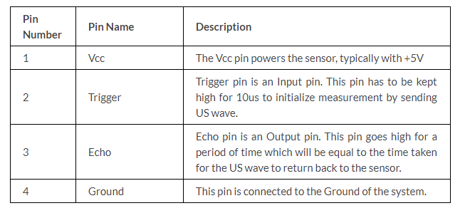
We have also interfaced a ultrasonic sensor which detects the obstacles on the path and controls the motion of the bot to avoid these obstacles.The ultrasonic sensor gives echo signal as output which
is a pulse modulated signal and the pulse width depends on the distance of obstacle infront of it. We have used the timer to measure the obtained pulse width. After measuring the pulse width, we
compare it with our obstacle threshold and give desired direction control commands to the bot.The details of Line follower and ultra sonic sensor are as follows:
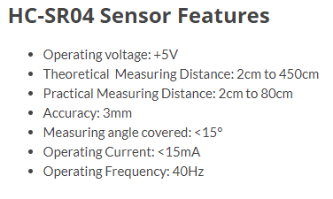
Ultrasonic Sensor HCSR04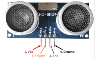
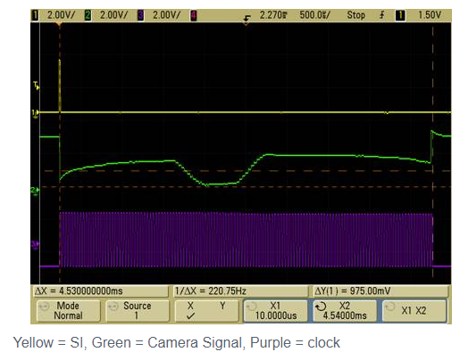
Line Camera Freescale
The line scan camera module consists of a CMOS linear sensor array of 128 pixels and an adjustable lens. This camera has a 1×128 resolution.
Once we have successfully determined the position of the black line, immediately adjust the wheels to adjust the direction of the car so that the black line will remain in the center of the camera’s view.
Sample camera output (for illustrative purposes only) The camera outputs an analog signal from 0 to 5V depending on the grey-scale value of the image. to simplify our sample we will assume that we have set limits for the line and have transformed the data to digital bits using a threshold value. 0’s are high intensity (non-line locations), 1’s are low intensity (black or line locations)
10000000000000000000000000000000001111101000000000000000000010000000000000000
Since the camera provides a 128×1 bit picture, and the camera will be pointing down at the track which is a fixed width. A control algorithm should be developed to line up the 1’s in the center of the 128 bits. The center of the field of view will be require calibration and testing, but it is assumed that the camera will remain in a fixed location pointing down the center of the forward looking axis of rotation.
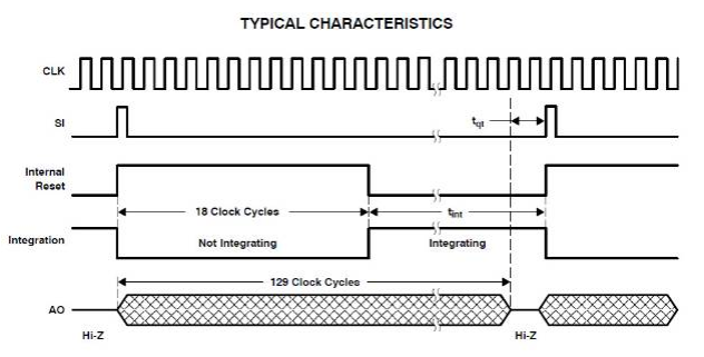
For normal operation of the camera, the following signals must be produced and processed:
CK (clock) – latches SI and clocks pixels out (low to high) continuous signal SI (serial input to sensor) begins a scan / exposure discrete pulses, pulse must go low before rising edge of next clock pulse AO (analog output) – Analog pixel input from the sensor (0-Vdd) or or tri-stated
The CK and SI signals are simple ON/OFF signals which can be produce using a GPIO Pin, setting the pin high and low corresponding to the desired exposure time of the camera. The only other requirement is to read the Analog Output of the camera which requires the initialization of the Analog Module and setting it to the proper pinout.
Conclusion
The mechanical structure of the robot was improved upon and balancing of the bot was corrected. However the balancing is not very effective still. Further Line camera and ultrasonic sensor were interfaced successfully with the bot and they are managed as separate tasks in RTOS.
Reference Code
https://github.com/LukeBoudreau/FreescaleCar/blob/master/camera.c
References
1. https://components101.com/ultrasonic-sensor-working-pinout-datasheet 2. https://community.nxp.com/docs/DOC-1030
Team Members
1. Raja Sharma 2. Vikneshwaran K
Recent Comments