
Objective
Given required location within the department, Robot should be able to guide a person to required location and returns to its original location which includes obstacle avoidance.
Working principle
Robot will be kept at a fixed location considering location as (0,0) and bot will be loaded with different locations of the department. A new visitor can select the required location in touch pad display. Based on visitor input bot will start from its location and take the visitor to required location and inform the visitor that destination is reached. After informing bot should come back to its original location. If bot found any obstacle in between it should halt till the obstacle moves away. Bot should move mostly in the middle of corridor.Here to move in middle of corridor and to avoid obstacle, three ultra sonic sensors were used. One is in front of robot to avoid obstacle and other two will be placed at two sides of bot which helps bot to go in middle of corridor. For a closed loop control over distance traveled, wheel encoders are connected to wheels which gives 32 pulses in one revolution of wheel. Based on number of pulses, distance traveled by bot can be estimated and as the path is fixed for specified destination, bot can be rotated or can be stopped. Touch pad display can be used to take inputs from visitor. To inform visitor after reaching destination, a speaker with DAC and amplifier can be used.
Components
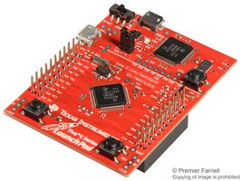
1. TIVA C Series Micro-controller (TM4C123GH6PM)
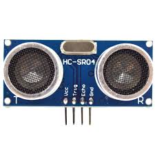
2. HC-SR04 Ultra sonic sensors – 3 nos
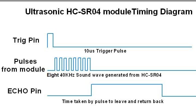
Timing diagram of HC-SR04 Ultra sonic sensors
3. Wheel encoders – 4nos
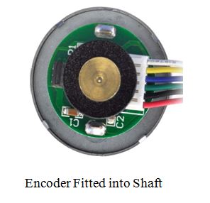
A two-channel Hall effect encoder is used to sense the rotation of a magnetic disk on a rear protrusion of the motor shaft. The quadrature encoder provides a resolution of 64 counts per revolution of the motor shaft when counting both edges of both channels.The Hall sensor requires an input voltage, Vcc, between 3.5 and 20 V and draws a maximum of 10 mA. The A and B outputs are square waves from 0 V to Vcc approximately 90◦ out of phase. The frequency of the transitions tells you the speed of the motor, and the order of the transitions tells you the direction.
The table below describes the each wire functionalities.4. 12Vdc motors – 4 nos
5. Motor driver
6. Rechargeable Battery
System specifications
Wheels: Type: Omni-Wheels, Diameter: 100mm.
Motors: Type: DC geared Motor, Rated volt: 12V, No load speed: 7000rpm, Rated Torque: 5.88mN.m, Rated current: 410mA, Rated speed: 5200rpm.
Encoders: Type: Hall Encoders(Incremental), Resolution: 301 pulses/rot, Volt: 5V.
Chasis: Material: Aluminum Alloy,Acrylic.
Drivers: Max Drive: 20A, Input Voltage: 7V to 18V.
Compass(GY-80): Type: 9-axis motion sensor, Communication: I2C.
Power Supply: Type: Ni-Cd, Voltage: 7.2V,2000mAh, Power Bank: 5V,3A.
Block Diagram
The figure below shows the connection block diagram of BOT
Operation:
1. DC geared motors are driven through PWM pulses generated by Timers – Timer 0A & Timer 0B on the TIVA board. Motor driver interface is used before these pulses are given to the wheel motors, which is used to match voltage and current driving capacity of the motors used to drive the wheels.
2. In order to track the distance travelled by the Robot, wheel encoders are used which are attached to motor shaft. On each rotation, these encoders produce finite number of pulses irrespective of speed of wheel (32 pulses per each rotation of wheel).This count is used to estimate the number of pulses to be given to motors in order to move for a specified distance.
3. Sensors are mounted on the front and the sides of the Robot. Front sensor is used for Obstacle detection, for Robot to halt in the presence of obstacle in front. Sensors mounted on the sides are utilized for PWM adjustment so that deviation in the path of motion of robot is detected and corrected accordingly.
RTOS implementation
FreeRTOS is used for implementation. The entire operation is implemented in RTOS for efficient and easy handling of various tasks. For this application, various tasks are as follows, 1. Forward movement of wheels along with wheel encoder processing as task1 2. Obstacle detection and direction correction as task2.
Task1:
In this task, PWM is generated using timers. For different wheels, different PWMs are generated. The duty cycle is selected as 50%, for which motion of Robot matches with the speed of human. Wheels encoders are mounted on each wheel. These wheel encoders will produce fixed number of pulses for each rotation of wheel. These pulses are counted and used for distance calculation. There are two outputs from each encoder. 1. Encoder output A(Inphase) 2. Encoder output B(Quadrature phase) Together a wheel produces 64 counts for each rotation. These two outputs can also be used for knowing the direction of motion of wheel. The encoder outputs are as below.. Currently, we are using only encoder A for distance calculation. For each rotation wheel produces 32 counts.
Distance travelled for one rotation = (number of counts/32)*2πr
where r is the radius of the wheel
Task2:
This task mainly focuses on the following activities.
1. Obstacle detection 2. Wheels PWM adjustment for direction correction.
– Obstacle detection:
We have mounted ultrasonic sensors HC SR04 which can detect any obstacle in the range 2cm to 4m distance. The front ultrasonic sensor is used for obstacle detection. Whenever there is an obstacle within a distance of 1m from front sensor, the robot should detect that obstacle and stop the movement. For this, all the ultrasonic sensors are activated by sending a trigger signal for about 10us, which is generated using timers. The echo signal from different sensors is captured on different wheels. The echo of the front sensor is used to calculate the distance of the obstacle. When the distance is less than 1m, then the wheels are stopped.
When the obstacle is cleared, the Robot is able start movement and it is able memorize the distance travelled earlier.
– Direction correction:
There are different factors that affect the wheel motion, a) The surface is one of the limiting factor, which will affect the wheel rotation. b) The PWM is given to the motor driver IC. Here two motor drivers are used and each one is able to control two wheels. Though both the drivers are powered from the same supply, there may be chance, that the wheels may get different voltages. In this case, there is difference in the voltages given to the wheels. This leads to a difference in the rotation speed of the wheels. For correction of these errors, the two ultrasonic sensors mounted on sides are used. When the robot moves close to wall on one side, the rotation speed of the opposite wheel is corrected. Similar procedure is employed for the wheel as well.
Task Switching:
Both the tasks are given equal priority. Each task runs for finite duration of time and yields for other task to run. This way we ensure that sensor task tracks the deviation of direction of robot periodically in order to correct the same, without affecting the motion of the robot. Hence, RTOS becomes handy in effective task scheduling to achieve the objective.
Experimental Set-Up and Results
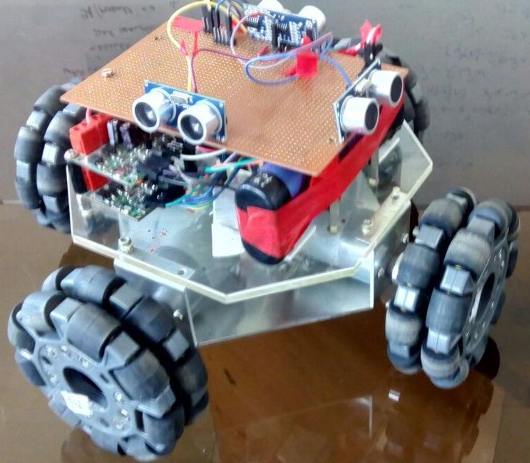
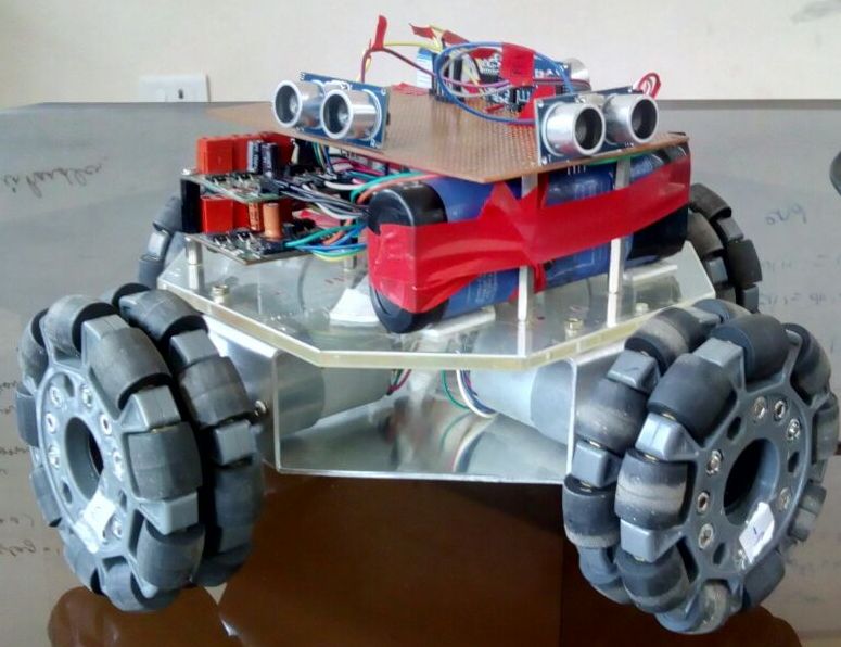
Practical view of Robot
Results: Hence the BOT is able to avoid the obstacles and determined different locations.
Future work
1)Further we can interface BOT with LCD for indicating different locations.
2)Speakers can be interfaced with BOT to inform visitor once reached.
3)It can also be expanded to different applications in industries like drug carrying by making small modifications in BOT.
link for the code
https://github.com/chandramoulibonela/Internal-navigation-Robot
References
[1]. Tiva™ C Series TM4C123G LaunchPad Evaluation Board(User’s Guide)
[2]. Tiva™ TM4C123GH6PM Microcontroller(Datasheet)
[3]. HC-SR04(Datasheet)[3]
Team Members
1) Gogineni Gopi Sunanth Kumar
2) Jahnavi Akula
3) Srividya Moka
4) Chandra Mouli Bonela
Recent Comments