
Objective:
The objective of the project is to demonstrate the application update without the use of a JTAG programmer. The user should be able to program the board with new application through a UART port connected to host pc. This Way user can update the application software without the need of dedicated jtag programmer and code composer studio sw suite.
Theory of Operation
The above objective is achieved by making use of the ROM bootloader available in TIVA TM4C123G processor. This is a dedicated ROM memory which contains the bootloader binary. This bootloader binary supports communication through UART0 of the processor. Once bootloader is active, connect the processor to host pc through UART port. An application in host pc shall communicate with bootloader to program the flash with new application software binary. This bootloader can be enabled by setting the EN bit in BOOTCFG register.
ARM Boot Sequence
The ARM CORTAX M4 Processor boot sequence is as follows
i. On hardware reset the arm core first reads the BOOTCFG register. This register contains the EN bit which enables/disables the ROM Bootloader. It also contains the GPIO, PIN & POLARITY bits which needs to be set in order to enable bootloader. These bits are meant to select a gpio pin which will be sampled by bootloader on HW reset to decide whether bootloader is forced start or not.
ii. If EN bit is set in BOOTCFG then processor looks for the state of GPIO pin. If the state of this GPIO pin is matching the polarity (as set in POLARITY bits) then bootloader will start executing and waits for the connection from host computer. Once host computer application starts it shall handshake with the bootloader and transfers the application software binary to bootloader. Bootloader shall first erase the flash and then program the flash with the new received binary file.
iii. If the state of this GPIO pin is not matching the polarity (as set in POLARITY bits) then bootloader will first check the contents of address location 0x00000000 & 0x00000004. If the contents of both these locations are not 0xFFFFFFFF (means there is a valid application exists at these addresses), then it loads the stack pointer SP with contents of 0x00000000 and loads program counter PC with contents of 0x00000004. then it starts executing from PC.
iv. If the state of this GPIO pin is not matching the polarity (as set in POLARITY bits) then bootloader will first check the contents of address location 0x00000000 & 0x00000004. If the contents of both/any one of these locations are 0xFFFFFFFF (means there no valid application exists at these addresses), then it starts bootloader & waits for host pc application for handshake and further programming of flash with nw application code.
Flash Partitioning
The TIVA TM4C123GH processor has 256KB flash. To meet the above objective we partitioned the flash in two parts as per following details
a. Part 1: It is 64K. This part is used to hold a default application / monitor code which shall be programmed initially and then will not be erased for subsequent software update. The idea behind it is that to have a default application always available in case the reprogramming of application binary fail for some reason.
b. Part 2: It is 192K. This part is supposed to hold the application code binary. This part can be reprogrammed whenever a new version of application code binary is available.
Planned Boot Sequence
a. First enable ROM boootloader & configure a GPIO (in this case we used PB0 polarity 1) in BOOFCFG register. you need to write a seperate code do this as this is one time activity (BOOTCFG is a non volatile register) and it shall not be part of any of the code. The procedure to write to BOOTCFG is mentioned in the processor datasheet (link in references).
b Write a monitor program which shall reside in part 1 of flash. Monitor program have Following functionality
  i. While starting monitor program in ResetISR, it checks for the content of locations 0x00010000 & 0x00010004.
  ii. If both locations content is not equal to 0xffffffff then monitor program does the following
      a. update Vector table offset register (VTABLE) to 0x10000
      b. update stack pointer SP with the content of location 0x00010000
      c. update program counter PC with the content of location 0x00010004 The program will leave monitor code and starts executing application code cation 0x00010000.
 iii. If either/both location content are equal to 0xFFFFFFFF then the monitor program continues and in main code starts blinking an LED. This indicates that there s no valid application exists at part 2 of flash and user need to program it again.
c. Write an application program with following updates
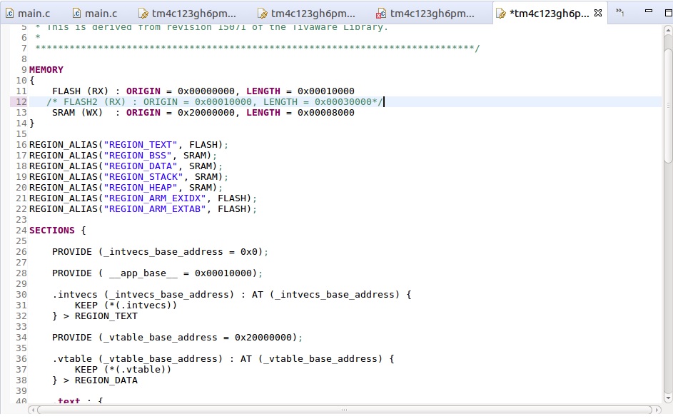
 i. Make following changes in the linker command file
    a. Update flash memory region to make it within part 2 of flash
    b. Update intvec table offset variable to 0x10000
d. Use host application sflash to communicate with bootloader to program part 2 of flash.
Method
Once we are ready with monitor program code and application program code, follow the below procedure to generate *.bin file which shall be needed by the host application to download to target board.
The following procedure is to be followed to create and update the application code
A. Create Application Code binary (.bin file)
1. Compile the application code in CCS. Once successfully compiled do the following changes in project properties
a. right click on application project name and click properties from pop up menu
b. In properties window left pane select GNU OBJCOPY Utility and then click on the check box
 'Enable GNU Objcopy Utility'
c. Now select General options under GNU Objcopy utility in left pane and fill as
 per the following picture
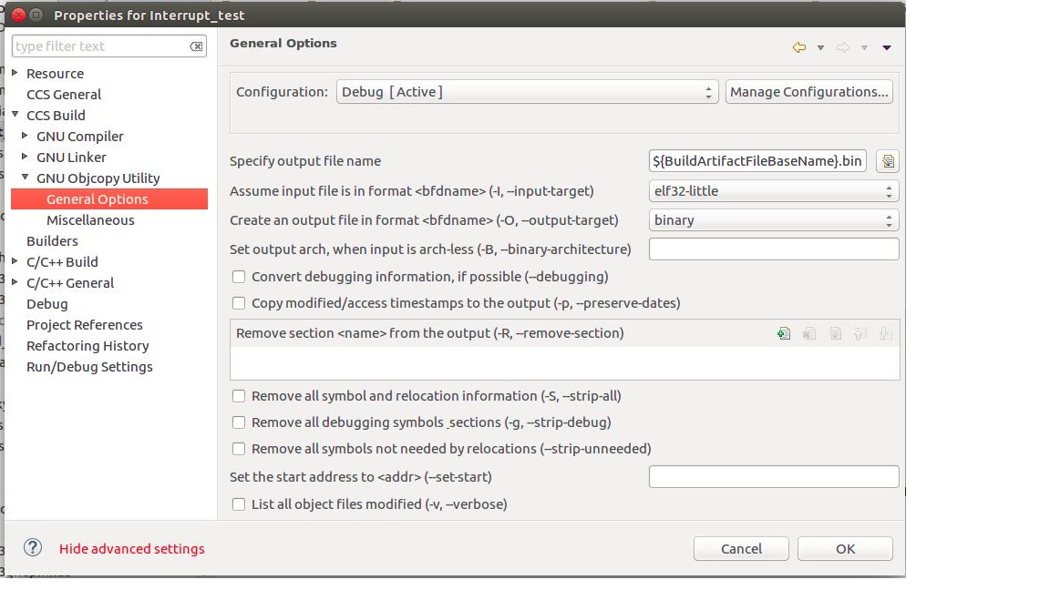
d. Press OK
2. Open the linker file (tm4c123gh6pm.lds) from your application project and update it as per following picture
3. Now compile the project again. This will create a <proj_name>.bin file in project/Debug directory
B. Create monitor code binary (.bin file)
1.Follow step A.1 above for objcopy settings.
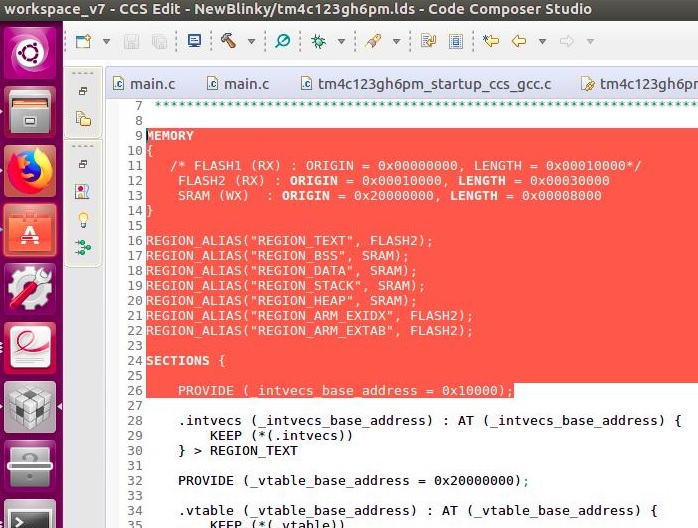
2.Open the linker file (tm4c123gh6pm.lds) of monitor project and update it as per following picture.
3.Now compile the project again. This will create a <proj_name>.bin file in project/Debug directory.
C. Program Monitor Code Binary in Flash
1. Now use CCS programming tool to program the monitor code binary in the board.
D. Program Application Code binary in the flash
1. First pull up the GPIO pin PB0 to make it logic ‘1’. Connect the UART0 of processor to host PC com port. Then reset the processor to enable ROM bootloader.
2. To program application .bin file use the host sflash application / GUI application. GUI application details mentioned in next section. You need give following inputs to sflash/GUI application.
a. Input file name : yourapplication.bin
b. com port number : /dev/ttyYoorPCPort (in linux)
c. program offset : 0x10000
3. After filling the details press program button of GUI. this will program the part 2 of flash with new code binary.
4. Now pull down the PB0 pin and reset the processor. This will run the application code.
Graphical User Interface:
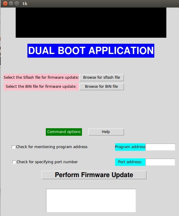
In order to perform the firmware update in a user-friendly manner, a graphical user interface (GUI) has been developed. The GUI has been developed using Python TKinter. Thus, instead on working on the terminal using commands, the user can work on an interface which enables in performing the following:
1) Select the sflash program which communicates with ROM boot loader via UART
2) Select the BIN file corresponding to the application to be downloaded to the flash
3) Specify the program memory address
4) Specify the UART communication port address
5) Run the firmware update
6) Additionally, a text box which displays the results of the operations done using the interface is provided (basically redirecting the information from command line).
A screen shot of the interface is shown below:
References
1. Tiva™ C Series TM4C123x ROM USER’S GUIDE SPMU367
2. Tiva™ TM4C123GH6PM Microcontroller DATASHEET SPMS376E
3. TivaWare™ Boot Loader USER’S GUIDE Literature Number: SPMU301D April 2013 – Revised July 2016
Recent Comments