
Seven-segment LED interfacing
The 7-seg LED can have common anode or common cathode.
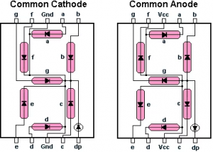
7 Segment LED – CC and CA
With common anode, the anode of the LED is driven by the positive supply voltage (HIGH) and the micro controller drives the individual cathodes LOW for current to flow through LEDs to light up. In this configuration, the sink current capability of the micro controller is critical.
With common cathode, the cathode of the LED is grounded and micro controller drives the individual anodes HIGH to light up the LED. In this configuration, the micro controller pins must provide sufficient source current for each LED segment. In either configurations, if the micro controller does not have sufficient drive or sink current capacity, we must add a buffer between the 7-seg LED and the micro controller. The buffer for the 7-seg LED can be an IC chip or transistors.
Displaying Letters

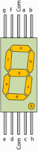
The seven segments of LED are designated as a, b, c, d, e, f, and g as shown in the figure:
A byte of data should be sufficient to drive all of the segments. In the example below, segment a is assigned to bit D0, segment b is assigned to bit D1, and so on as shown below:
| Assignments of port pins to each segments of a 7-seg LED | |||||||
| D7 | D6 | D5 | D4 | D3 | D2 | D1 | D0 |
| . | g | f | e | d | c | b | a |
The D7 bit is assigned to decimal point.
One can create the following patterns for numbers 0 to 9 for the common cathode configuration:
| Segment patterns for the 10 decimal digits for a common cathode 7-seg LED | |||||||||
| Num | D7 | D6 | D5 | D4 | D3 | D2 | D1 | D0 | Hex Value |
|---|---|---|---|---|---|---|---|---|---|
| 0 | 0 | 0 | 1 | 1 | 1 | 1 | 1 | 1 | 0x3F |
| 1 | 0 | 0 | 0 | 0 | 0 | 1 | 1 | 0 | 0x06 |
| 2 | 0 | 1 | 0 | 1 | 1 | 0 | 1 | 1 | 0x5B |
| 3 | 0 | 1 | 0 | 0 | 1 | 1 | 1 | 1 | 0x4F |
| 4 | 0 | 1 | 1 | 0 | 0 | 1 | 1 | 0 | 0x66 |
| 5 | 0 | 1 | 1 | 0 | 1 | 1 | 0 | 1 | 0x6D |
| 6 | 0 | 1 | 1 | 1 | 1 | 1 | 0 | 1 | 0x7D |
| 7 | 0 | 0 | 0 | 0 | 0 | 1 | 1 | 1 | 0x07 |
| 8 | 0 | 1 | 1 | 1 | 1 | 1 | 1 | 1 | 0x7F |
| 9 | 0 | 1 | 1 | 0 | 1 | 1 | 1 | 1 | 0x6F |
EduARM4 Board 7-Segment LED Interface
Jumper Selection:
J5 – Short 1 & 2
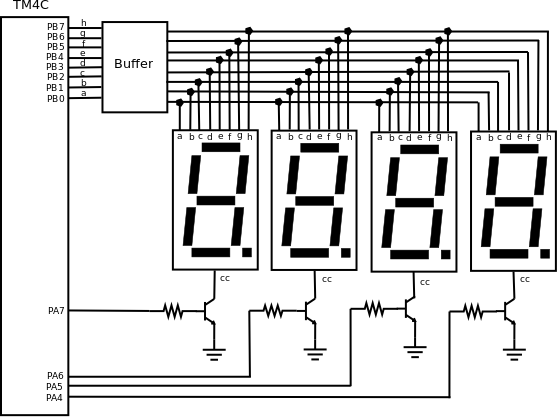
Since the same segment for four digits are connected to the same I/O port pin, the common cathode of each digit must be driven separately so that only one digit is ON at a time. The 4-digits are turned on one-by-one at a time . For example, if we want to display number 14 on the 7-seg LED, the following steps should be used:
- Configure Port B (PB0 – PB7) as output port to drive the segments
- Configure Port A (PA4 – PA6) as output port to select the digit
- Write the pattern of numeral 1 from the above table to Port B
- Write one bit of Port A to activate the tens digit
- Delay for some time
- Write the pattern of numeral 4 from the above table to Port B
- Write one bit of Port A to activate the ones digit
- Delay for some time
- Repeat from step 3 to 8
At low frequency of alternating digits, the display will appear to be flickering. To eliminate the flickering display, each digit should be turned on and off at least 60 times per second.
Notice in the above figure, a single pin is used to select each digit. That means for 4-digits we have used a total of 12 pins i.e, 8 pins for the segments a through g, decimal point, and 4 pins to select each digit.
See Also
Task
- Implement minutes and seconds using software Delay and Display it on the 4-digit 7-segment LED
Recent Comments