
Problem Statement
Three Phase Energy Meter
The purpose of this project is to develop a 3-phase Energy Meter, using TIVA TM4C123G6PM microcontroller board and MCP3903 ADC IC from microchip, used to perform all the measurements in the energy meter. Basically, the energy meter is designed to measure the energy, equivalent to the power consumption over time, using the formula of P = V * I. Therefore, for each phase two input channels are connected to the ADC chip, one for voltage, and another for current. Analog signals will be detected from the two input channels, which will be converted into Digital signals by ADCs respectively. With the two digital input signals transmitted to the microcontroller via SPI protocol, TIVA calculates the power hence, energy consumed will be accumulated after a specified period of time. The microcontroller is programmed with C language; ADC channels are used for converting both current analog signal and voltage analog signal; multiply algorithm is used to process the power and energy, voltage and current signals based on the energy formula and many parameters are displayed such as voltage, current, Active power.
Hardware Description
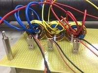
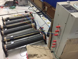
Three Phase current Transformers
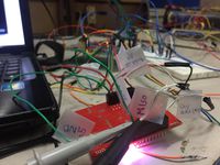
The hardware includes TM4C123G6PM microcontroller unit, MCP3903 ADC IC for analog to digital conversion of 3-phase voltage and current inputs, external oscillator of 3.2768Mhz acting as clock to energy meter ICs(MCP3903), Three phase voltage signals are connected to the meter through a 3-phase auto transformer and to the MCP3903 A/D converter through a voltage divider circuit. The currents are measured using three current transformers. The sampling of the signal as well as analog-to-digital conversion is performed using the device MCP3903 which sends the digital converted results to the microcontrolller device through SPI interface. The load current can be varied through a rheostat.
The MCP3903 samples all the 6 channels simultaneously and converts them to 24-bit values. The sampling frequency is 500 Samples/sec. This translates to a datarate of 500*6*24 Bits/sec. The data is read-out using the implemented software SPI block in the MCU.
Implementation Details
MCP3903 and supporting circuitry
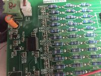
A. Analog Inputs to MCP3903 IC
The front-end of the meter is made up of three pairs of voltage and current input networks. Each of the three line voltages is attenuated by a resistor divider and filtered through identical first order low pass filters.The current channels signals are converted from current to a voltage through current transformers and burden resistors. The voltage developed across these resistors are read out by the ADC.
B. Analog to Digital Conversion This meter design uses Microchip’s MCP3903 energy meter ICs. Small-signal inputs can be amplified by the programmable gain amplifier inside the MCP3903 device. Currently gain is set as 1. The MCP3903 device’s clock is provided by a 3.3768 MHz active crystal. The MCP3903 device’s output data rate is 96Kbps.
B. Communication Protocol Used The MCP3903 communicate with other devices using SPI. It is configured as a slave and Address based register reads can be done.
Software Implementation
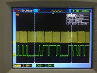
SPI CLK and MISO
The software is to have an overall control of the hardware at all time and to determine the current, voltage, power and energy based on the principles of power and energy calculations.
SPI Implementation A software SPI was implemented in C. This was used to configure the slave ADC and read its registers. The TIMER0 peripheral generates the SPI CLK and GPIO write and read was used for MOSI and MISO respectively. The CS pin was made low for the entire communication duration. The SPI CLK oscillates at 125KHz.
Sampling The sampling rate was fixed at 500 Samples/sec. We need to sample every 2ms. This was achieved by TIMER1 interrupts. Every time an interrupt request was issued, a command was given to invoke 6 reads from MCP3903.
-> This implementation requires that the TIMER0 interrupt needs to have a higher priority compared to TIMER1.
Energy Calculation A function Start_Calculation() was invoked which samples 100 samples each for the 6 channels. The corresponding currents and voltages are multiplied for each sample and the average of all the samples gives the average power.
The energy consumption is the cumulative sum of the above average power scaled by a time factor.
This cycle repeats.
Results obtained
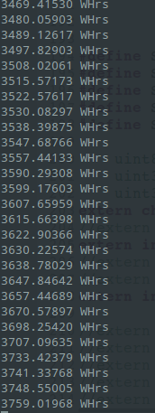
Energy Consumption Displayed on UART interface
Initially the protocol was successfully analysed and implemented.
The currents and voltage values were calibrated. The final Energy reading was displayed in the UART interface.
References
[1] MCP3903 Datasheet- www.microchip.com/downloads/en/DeviceDoc/25048B.pdf
[2] SPI Bus Documentation- en.wikipedia.org/wiki/Serial_Peripheral_Interface_Bus
[3] Joseph Yiu- The Definitive Guide to the ARM Cortex-M3
Three Phase Auto Transformer
Recent Comments