
Problem Statement
Design a user interface to read the value from BOOSTXL-SENSHUB BOOSTERPACK and display on kentec QVGA touch screen graphics display with TIVA c series launchpad.
Resources
- TIVA C Series Microcontroller (TM4C123GH6PM).
- Kentec QVGA Touch Screen Graphics Display.
- Code Composer Studio IDE.
- GCC.
- BOOSTXL-SENSHUB BOOSTERPACK.
Project Overview
Here we designing the LCD interface with multiply touch buttons on it(i.e one button for each sensor).depending on which button is tapped sensor sense the data and send it to the LCD Display
Block Diagram
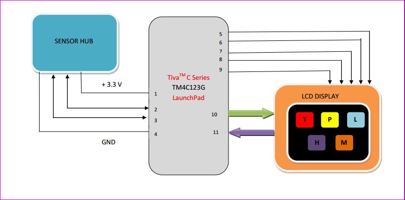
Description
- Power Supply Pin(3.3V).
- I2C Clock pin(I2CSCL).
- I2C Data pin(I2CSDA).
- Ground Pin.
- Power supply to Display.
- Ground to Display.
- Reset.
- SPI clock input for LCD.
- Chip select signal input for LCD.
- SPI data input for LCD.
- Resistive touch screen data input for micro-controller.
Understanding GLCD interfacing
Introduction
The BOOSTXL-K350QVG-S1 Kentec QVGA Display BoosterPack is an easy-to-use plug-in module with a touch-screen color display.We can use this BoosterPack to start developing applications using the 320×240-pixel TFT QVGA display with resistive touch screen.It uses SPI for communication.
Key Features
- Kentec TFT LCD (part number: K350QVG-V2-F)
- 3.5-inch QVGA (320×240 resolution)
- SPI communication
- 4-wire resistive touch screen
- White LED backlight
- LED backlight driver circuit
- Complies with the BoosterPack standard for use with 20- and 40-pin LaunchPads.
BOOSTXL-K350QVG-S1 Interface
The pin connections to EK-TM4C123GXL is as shown below in tables.
| J1 Pin | Symbol | Description | Note |
|---|---|---|---|
| 1 | 3.3 V | Power supply | |
| 2 | NC | No connection | |
| 3 | NC | No connection | |
| 4 | NC | No connection | |
| 5 | NC | No connection | |
| 6 | NC | No connection | |
| 7 | LCD_SCL | SPI clock input for LCD | |
| 8 | (LCD_SDC) | 4-wire SPI mode DC input for LCD | |
| 9 | NC | No connection | |
| 10 | NC | No connection |
| J2 Pin | Symbol | Description | Note |
|---|---|---|---|
| 11 | TOUCH_YN | Resistive touch screen terminal (Bottom) | |
| 12 | NC | No connection | |
| 13 | LCD_SCS | Chip select signal input for LCD | |
| 14 | NC | No connection | |
| 15 | LCD_SDI | SPI data input for LCD | * |
| 16 | RESET | Reset signal for MCU | |
| 17 | NC | No connection | |
| 18 | NC | No connection | |
| 19 | NC | No connection | |
| 20 | GND | Ground |
| J3 Pin | Symbol | Description | Note |
|---|---|---|---|
| 21 | 5V | Power Supply | |
| 22 | GND | Ground | |
| 23 | TOUCH_YP | Resistive touch screen terminal (Top) | |
| 24 | TOUCH_XP | Resistive touch screen terminal (Left) | * |
| 25 | NC | No connection | |
| 26 | NC | No connection | |
| 27 | NC | No connection | |
| 28 | NC | No connection | |
| 29 | NC | No connection | |
| 30 | NC | No connection |
| J4 Pin | Symbol | Description | Note |
|---|---|---|---|
| 31 | TOUCH_XN | Resistive touch screen terminal (Right) | |
| 32 | LCD_RST | Reset signal input for LCD | |
| 33 | NC | No connection | |
| 34 | NC | No connection | |
| 35 | NC | No connection | |
| 36 | NC | No connection | |
| 37 | NC | No connection | |
| 38 | NC | No connection | |
| 39 | NC | No connection | |
| 40 | LED_ON/OFF | LCD backlight ON/OFF control. |
- *look into description of EK-TM4C123GXL image
The following are the images of GLCD Display,micro-controller and their interface.
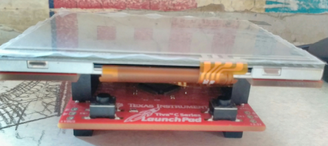
Interfacing:LCD is mounted on controller
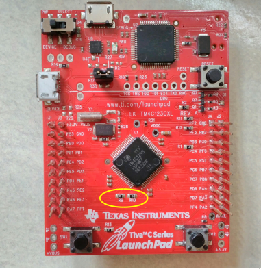
EK-TM4C123GXL:The yellow circle highlights the R9 and R10 registers.This registers should be removed because for the Tiva C Launchpad / EK-TM4C123GXL application, “LCD_SDI / PB7”has been connected to “TOUCH_XP/PD1” by “R10” on the Launchpad.You must remove “R10” before application
BOOSTXL-SENSHUB BOOSTERPACK Interface
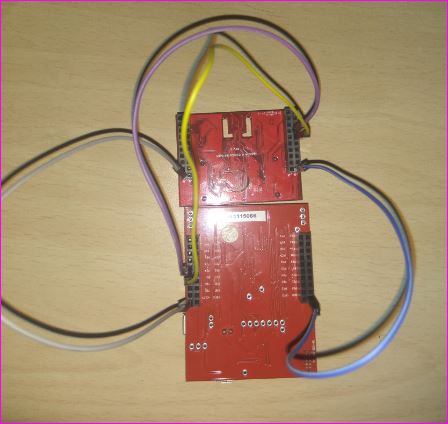
4 pins are required to interface sensor hub to controller as follows
- Sensor hub Pin J1.1 is connected to 3.3V of controller.
- Sensor hub Pin J2.1 is connected to GND of controller.
- Sensor hub Pin J2.7 is connected to PE4 of controller.
- Sensor hub Pin J2.6 is connected to PE5 of controller.
The following are the images of BOOSTXL-SENSHUB BOOSTERPACK,micro-controller and their interface.
Sample Screenshot
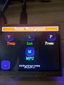
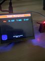
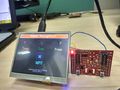
Procedure
- First we made the above said connections between Tiva Launchpad and sensor board and LCD display.
- Then we made queues for touch,LCD and sensor hub task in RTOS environment.
- Then when we press the button of corresponding sensor on the LCD display,as soon as as button is pressed the corresponding pressed tab information is stored in the touch queue.
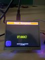
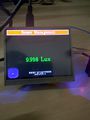
- The touch task then sends the same information to the sensor hub queue.
- Now depending on the message in the sensor hub queue ,corresponding sensor value is written back to the LCD queue which then writes back to the touch queue.
- On the screen the corresponding sensor value is displayed.
- Similarly, when we press another sensor tab on the LCD display, it’s value will be displayed.
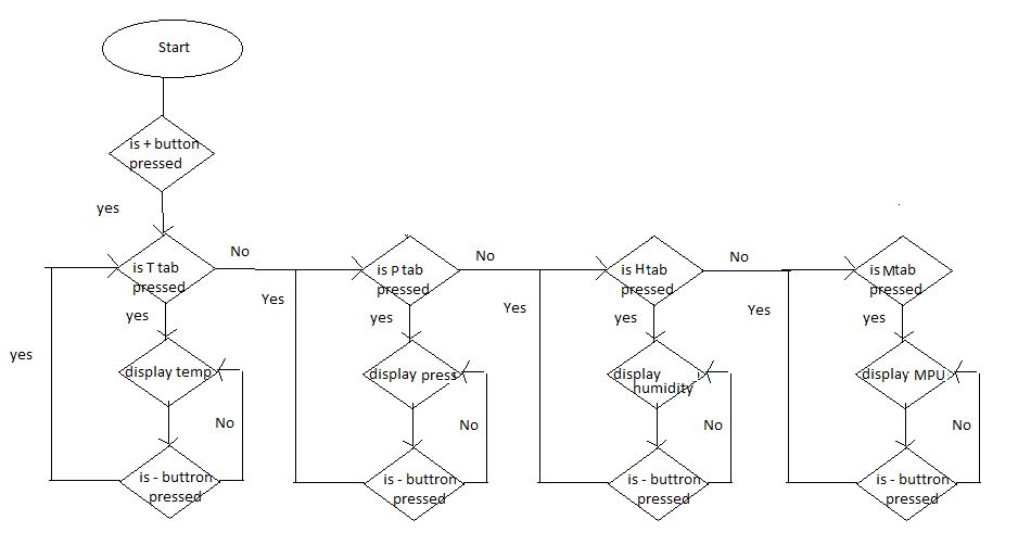
Flow Chart
References
- BOOSTXL-K350QVG-S1 QVGA Display BoosterPack™ Plug-in Module – http://www.ti.com/lit/ug/slau601a/slau601a.pdf
- TivaWare™ Peripheral Driver Library (User Guide)
- Tiva™ TM4C123GH6PM Microcontroller(Datasheet)
- Tiva™ C Series TM4C123G LaunchPad Evaluation Board(User’s Guide)
- TivaWare™ Graphics Library(User’s Guide) –http://www.ti.com/lit/ug/spmu300d/spmu300d.pdf
- TivaWare ™ Graphics Library Display Drivers –http://www.ti.com/lit/an/spma055/spma055.pdf
- BoosterPack (BOOSTXL- K350QVG-S1) – http://www.kentecdisplay.com/uploads/soft/Products_spec/BOOSTXL-K350QVG-S1_UserGuide_04.pdf
Team Members
Hirak Biswas
Ahankar Kamble
Shresth Gupta
Recent Comments