
Project Concept:
This project aims at building a two wheel self-balancing robot based on the concept of
inverted pendulum and the application of a PID control system. Self-balancing bots are
robotic devices that are capable of maintaining an upright position on two wheels. This
is achieved by collecting data from the accelerometer and gyroscope and using control
algorithms to balance the bot. This project is inspired by the Segway, which makes use
of movements by the body for steering purposes where the centre of mass is located
above the pivot.
The bot was implemented using the TivaTM C series TM4C123GH6PM microcontroller
from Texas Instruments. Offset calibration was done by trial and error methods by
serially displaying the values from sensors through UART. PID tuning was performed
through Ziegler-Nichols method. Moreover, I2C communication was used to receive
values from MPU6050 sensor and PWM signals were generated accordingly to control
the motors.
Implementation Details:
The bot was implemented using the TivaTM C series TM4C123GH6PM microcontroller
from Texas Instruments. Offset calibration was done by trial and error methods by
serially displaying the values from sensors through UART.
Moreover, I2C communication was used to receive values from MPU6050 sensor and
PWM signals were generated accordingly to control the motors. A solution to this is
fusing both the accelerometer and gyroscope values and this can be done with the use
of filters. In control theory, complementary filters are widely used for this purpose as
its implementation is simple
COMPLEMENTARY FILTER
The idea behind complementary filter is to take less fluctuating (slow moving) values
from accelerometer and tilt sensitive (fast moving) values from a gyroscope and
combine them. Accelerometer gives a good indicator of orientation in static conditions.
Gyroscope gives a good indication of tilt in dynamic conditions.
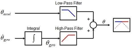
So the idea involves, passing the accelerometer signals through a Low pass filter and
the gyroscope signals through a High pass filter and combine them to give the final tilt.
The equation of complementary filter is given by:
Angle = (1-α)*(angle + gyro*dt) + (α)*(acc)
The error is evaluated as the difference of present angle and previous angle and
this error acts as an input to the PID control block. This is an example of closed
loop control system also referred to as the negative feedback system. The PID
control then outputs a correction factor as
Correction = Kp * present error + Ki * total error + Kd * (present error –
previous error)
The following table enlists all the mechanical components that were required.
1. MPU6050 sensor (3 axis accelerometer, 3 axis gyroscope)
2. TIVATM C series TM4C123GH6PM MCU from Texas Instruments
3. L298N motor driver
4. 12v DC motors (6mm shaft diameter)
5. L Clamps for motors
6. 11.1 V (3 cell) LiPo battery, charger and switch
7. 7805 voltage regulator
8. 80 mm diameter wheels
9. 5cm long; 3mm screw size Hexagonal brass (male and female) spacers
10. 12mm Hex Wheel Adapter for 6mm Shaft
11. 18cm X 11cm Acrylic sheets for chassis of the bot
12. Bread Board
13. 3mm bolts and nuts
14. female to female jumper wires
15. rolls of single strand connection w
Components used:
TivaTM TM4C123GH6PM MCU
Manufactured by Texas Instruments, this board is a high performance 32 bit,
ARM® Cortex®-M4F-based microcontroller. It is targeted for industrialapplications
like remote monitoring, network appliances, factory automation,
HVAC and building control, gaming equipment, motion control, transportation,
and security.
Its features include an 80MHz processor core with system timer (SysTick),
integrated nested vectored interrupt controller (NVIC), wake-up interrupt
controller (WIC) with clock gating and memory protection unit (MPU).
Moreover, it has Advanced serial integration featuring eight UARTs with IrDA,
9-bit, and ISO 7816 support along with advanced motion control featuring eight
pulse width modulation (PWM) generator blocks, each with one 16-bit counter,
two PWM comparators, a PWM signal generator, a dead-band generator, and an
interrupt/ADC-trigger selector.
Also provides analog support featuring two 12-bit analog-to-digital converters
(ADC) with 12 analog input channels and a sample rate of one million
samples/second, two analog comparators; 16 digital comparators, and an on-
chip voltage regulator.
MPU6050:
One of the most significant components in building a self-balancing bot is an
accelerometer and gyroscope module. We have used this high precision, 3 axis
gyroscope and 3 axis accelerometer to measure the angle of deviation. This
devices are small in size and very cheap to buy. But, they share their own
disadvantages.
Gyroscopes are good for short term and quick movements but tend to drift over
time as the error accumulates. Whereas accelerometer is good at sensing slower
and more prolonged movements. Hence these two sensors need to be fused to
read out accurate measurements using filtrations.
This modules uses I2C to communicate with the microcontroller and needs 3.3
v to input voltage. The measurement ranges for the accelerometer are +/-2g, +/-
4g, +/- 8g , +/-16g and for the gyroscope are +-250/500/1000/2000 dps.
L298N Motor driver:
The L298N driver is a high voltage, high current dual full bridge driver designed
to accept the standard TTL logic levels and can drive inductive loads such as dc
motors, stepper motors, relays and solenoids.
Since the microcontroller operates at a low voltage and current whereas the
motors requirements are higher, the driver acts as a current amplifier. The
maximum supply voltage is 46v and maximum output dc current is 4a.
It has practically all the features that are required in a good motor driver,
including thermal-shutdown, as in it will slow down and stop if overloaded.
SOFTWARE:
I2C (Inter-Integrated Circuit) Communication:
1. There can be multiple masters and slaves connected together while only a
master and a slave can communicate at once over a channel.
2. Used to integrate devices of different speeds.
3. Each slave has a unique slave address which is used by master to
communicate the data to a particular slave.
4. The data transfer from master to slave is serial and it is split into 8-bit packets.
5. It uses just 2 wires SCL (Serial Clock) and SDA (Serial Data).
6. Communication is initiated by master device which generates the start
condition followed by slave address. There is a bit specifically assigned to
mention the task being performed i.e. read (1) or write (0) by the master along
with sending the slave address. Once all the bytes are read or written the master
generates a stop condition indicating the end of communication.
Initialization of MPU6050
In here we are setting limits to 16bit ADC of the sensor as +/- 250dps and +/- 2g
so as to get more precise values and being sure that values from sensor to our
project will be within the limits. Look into the datasheet of MPU6050 to
understand the below configuration.
I2C just has a wire using which we can configure the slave device. It is done by
first sending the slave address which has to be configured followed by address
of the register of slave we want to configure followed by the values to be written
or read from the register.
Interrupt
An interrupt is a signal to the processor emitted by the hardware or software
indicating that an event needs immediate attention. Whenever an interrupt
occurs, the controller completes the execution of the current instruction and
starts execution of an Interrupt Service Routine (ISR ) or Interrupt Handler
which is a program written to guide the controller about what has to be done
when an interrupt occurs.
In here, as there can be only one master and a slave at a time and as we
have 2 slaves (Motor Driver and MPU6050) we need to regularly switch
between the two. So here we have used interrupt to stop reading values from
MPU6050 at every 20ms and then send the PWM to the motor driver.
Conclusion:
The values of the sensor (MPU6050) have been rectified to almost idealism and
ready to use with necessary offsets in the codes. The values are then fused to get the
best estimate of the tilt angle using Complimentary Filter. A basic understanding of
the Kalman Filter has been achieved by verification of tilt angle estimation on UART
but it being computationally cumbersome isn’t being used. The tilt angle estimated
is PID tuned to direct the wheels to stabilize in upright position. The robot’s physical
design has been completed and the progress has been achieved to date as planned.
Demo: video link
code: BALANCING_BOT
Recent Comments