
Artificial Neural Network Based Distress beaconing, messaging
and tracking system by detecting gesture and body state cues
1 PROLEM STATEMENT
In extreme distressful conditions or impending danger and time critical
conditions , it would be difficult for any person to inform the closed ones about the
situation
The person , in most of the cases , might not be in a position to take out the phone
, unlock , and then dial the number (or type messages ) , mentioning the plight .

The situation becomes worse when one realizes that the phone is almost out of
battery / or the phone is snatched.

In such cases its important to automatically inform the concerned people
regarding the state of the victim , by detecting bodily functions and gestures
In such cases its important to automatically inform the concerned people
regarding the state of the victim , by detecting bodily functions and gestures.
In such cases there are few things that happens invariably
Pulse Rate Variations
Body temperature Variations
Vocal Expressions and Body gestures Variations
So we attempted to solve the problem by taking cues from the above parameters
Monitoring the pulse rate : From the wrist/finger
Body temperature : the radial artery (RA) region, ulnar artery (UA) region, and
upper wrist (UW)
Vocal Expressions and Body gestures ( through IMU sensor and Microphone)
Send SMS to the numbers which are stored informing about the distress along with
the GPS coordinates.
2 DESCRIPTION
The project aims at increasing safety and automatic information sending thereby
reducing communication setbacks during critical and distressful situations .
There are some critical pointers though which needed to be taken care of during the
development :
1.Low Power for extended battery life
2.Types of data to be acquired
3.Dealing with false positives
4.Deciding a data fusion algorithm
5.Deciding the interface for sending the distress signal
6.Deciding on sensors and interfaces
Low Power for extended Battery Life :
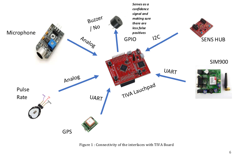
Cortex M4 based processor TM4C123GH6PM was chosen because of its low power ,
sleep to wake up features and diverse in-built interfaces making integration easier . The
board which was chosen was TIVA LaunchPad
Types of data to be acquired:
The data we decided upon to detect the state of the person in distress would be :
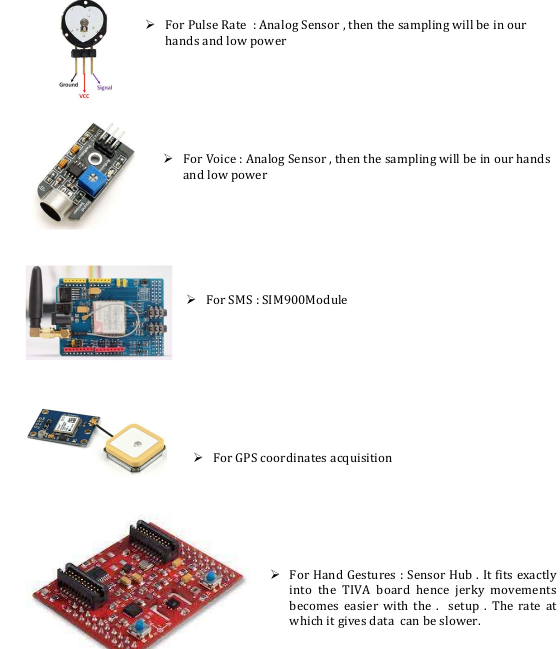
1. Pulse Rate Data
2. Voice Data
3. IMU data for hand movements (X acceleration , Y acceleration , Z acceleration)
Deciding on a data fusion algorithm :
The data fusion algorithm for the varied data mentioned above would be complex . So
Neural Network Based architecture was decided to blend all the data and take the
decision
Dealing with False Positive :
A buzzer was kept which served as a confidence signal and a false positive detector signal
. The vibration of the buzzer would be felt only by the person who is wearing it .
In distress situation : It will serve as a confidence signal and a cue to the victim , that
the distressful situation has been detected by the device and the distress beacons will
be definitely sent .
In case of false positives : In case the device misinterprets a normal situation as
distressful situation , it vibrates the buzzer . The user can stop the device operation within
some time limit so that the distress beacons are not sent.
Deciding the interface for sending the distress signal
Sms mode along with GPS coordinates was chosen as an interface for sending distress
signals . Other interfaces would either require smart phone or wifi signals .
Deciding on the important sensors and interfaces :
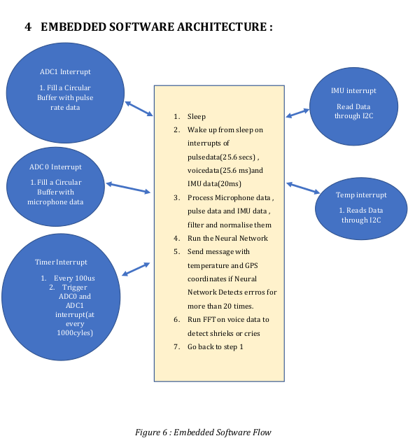
Overview of the Software
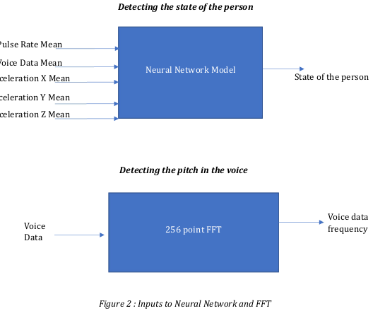
Idea is to take different “types” data and then feed it to some kind of black box , fuse the
sensor data and then determine the state of the person.
The identified inputs were :
1. Pulse Rate Mean
2. Voice Data Mean
3. X Acceleration Mean
4. Y Acceleration Mean
5.. Z Acceleration Mean
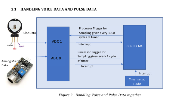
It is possible to initiate conversion on both the ADCs from two different timers but then
dynamic change of sampling rate is difficult
That’s why A timer is used to generate interrupt at 100us and then processor trigger is
used to trigger sampling in the ADC’s , that way different sampling rates can be generated
from a single timer and the sampling rate can also be changed on the fly without any
reinitialization of the timers.
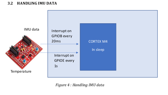
The temperature and IMU data is handled through separate interrupts coming at 50Hz
and 1Hz . The interrupts from the data ready signal after conversion and is triggered in
GPIO.
3.3 SOFTWARE PROCESSING OF DATA FOR THE NEURAL NETWORK
1. The raw voice data is collected at every 25.6 ms (for 256 samples sampled at 10K)
and put in a ring buffer for further processing
2. The voice data is corrected for bias , rectified and then passed through an IIR filter
to detect the mean value
3. The raw pulse data is collected at every 25.6 s (for 256 samples sampled at 1Hz)
and put in a ring buffer for further processing
4. The pulse data is corrected for bias , rectified and then passed through an IIR filter
to detect the mean value.
5. The IMU data comes at every 50Hz is corrected for bias then passed through
balanced filters to correct for the noise and then rectified , and passed through IIR
filter for the mean
6. The IIR filter is present in all the data processing to smoothen out for some spikes
in the data.
7. All the mean data are normalised first by dividing by their max value (empirically
decided) and then fed to the Neural Network
8. The training data was generated in TIVA board , imported in MATLAB and the
model was trained in MATLAB
9. Finally the weights and biases were exported back to TIVA board and then the
NEURAL Network was tested in real time.
Network architecture is –
Feed-forward, multi layered ,fully connected Perceptron model
No. of Layers : 4
1 input layer
2 hidden layers
1 output layer
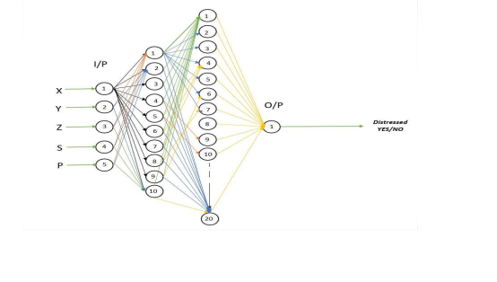
3.3.1 NEURAL NETWORK PARAMTERS
No. of Input Node = 5
No. of Neurons in hidden Layer 1 = 10
No. of Neurons in hidden Layer 2 = 20
No. of Output node = 1
Training /Learning rate = 0.01
Epochs = 50
Batch Size = 10
Activation Function – Relu
Loss Function : Cross Entropy / Log Loss
Based on Gradient Descent Back Propagation Algorithm
Training Data Set – 59049 set of Input variations
Inputs = XAcc, YAcc, ZAcc, Pulse, Sound
Each varying from 0 to 1 trained
All inputs are scaled down/up to 0 to 1 to get output
Output is 1/close to 1 if any value of input above 0.7
Output is 0/close to 0 if all the inputs are less than .7
Weights and Biases
W12 – 10 x 5
W23 – 20 x 10
W34 – 1 x 20
B12 – 10 x 1
B23 – 20 x 1
B34 – 1 x 1
Total no. of single precision data = 301
Total memory space required = 1204 bytes
3.4 SOFTWARE PROCESSING OF DATA FOR THE FFT
256 samples of the voice data is collected every 25.6 ms and then short term
fourier transform is calculated in that .
FFT function coded can –
o Compute the fft of a complex vector.
o Store the results back in same vector
o Work only if power of 2 is the vector size
o Uses Cooley Tukey Decimation in Time Radix 2 algorithm
o We are using FFT to compute the frequency components of sound data and
singling out frequencies which have higher magnitudes.
FFT algorithms input is fixed at 256 samples of data essentially making this fft
implementation an STFT (Short time Fourier Transform)
This STFT has a rectangular windows which means samples are taken as it is
without any modifications to magnitude of input
These 256-input vector will give us a 256 sized complex vector results of FFT.
This 256 sized complex vector is then converted to absolute values
Then again folded into a one-sided frequency response
While folding all magnitudes are compared against a reference of 600 to single out
frequency components and their corresponding indices are noted
The indices are then viewed in frequency which is from 0 to 5kHz owing to the
fact that our sampling rate is 10 kHz
Challenges :
1. Generating the training data took time and effort . Voice and Pulse rate training data
was particularly difficult as it changed over the course of the day.
2. Availability of Resources during the pandemic situation . Had to order everything
online and was unsure of the quality
3. Writing the drivers from scratch for every interface was time taking.
4. Pulse data was really noisy . The IIR filters coefficients choice took time and effort
5. The acceleration data required complementary filtering for stability . The acceleration
data used to get stuck thereby triggering false positives in the Neural Network .
Future Scope :
1. Using own developed RTOS from scratch (which was a part of the assignment) to
schedule the tasks from scratch .
2. Use of Fixed Point instead of Floating Point
3. Use of DSP instructions instead of normal multiplication instruction
4. Implementation of both training and inference in the embedded platform
5. Use of SVM instead of ANN to minimise the multiplication .
6. Increasing the sleep cycle of the processor and working at lower frequencies to
maximise battery life.
Demo:
Recent Comments