
Alive object detection using PIR, Ultrasonic sensors and
using TM4C123GH6PM
1.Introduction:
The main objective of the project is to detect the movement of alive objects around the
embedded system and also to calculate the distance and angle of objects around the embedded
system.
The embedded system designed in this project contains two PIR sensors, which are
present on the left and right side of the system. And, the system also contains a stepper motor
with an ultrasonic sensor mounted on it. The PIR motion sensors detects the motion of alive
objects on left side or/and right side. Accordingly, the stepper motor rotates in anti-clockwise
direction or clock wise direction to scan the left or right side of the system. When the stepper
motor is rotating, the ultrasonic sensor mounted on it is used to send the pulses and the reflected
signals are captured to calculate the distance to the objects around the system.
2.Circuit Diagram
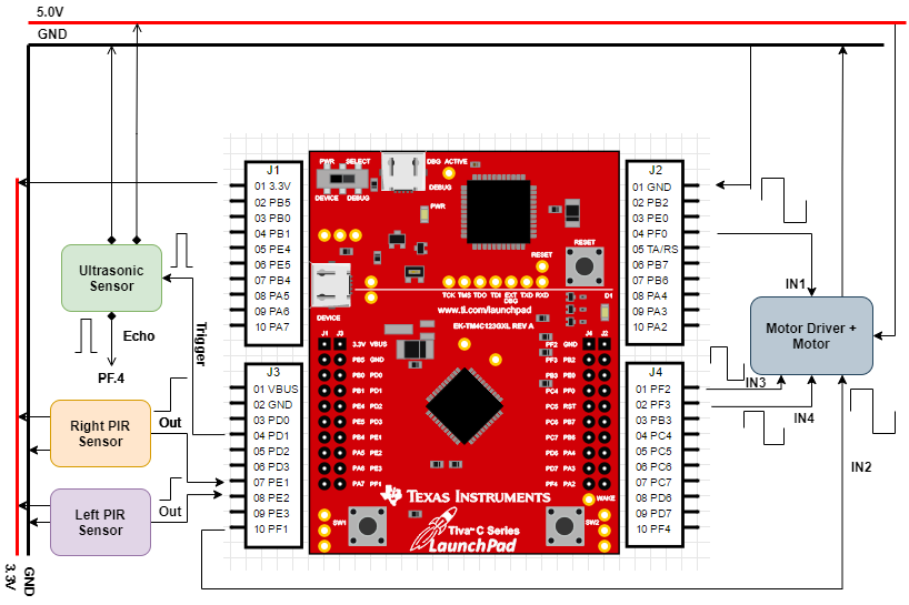
The given EduARM4 Trainer Board has a 16×2 LCD Display and four seven segment
displays. Both the LCD and Seven Segment Display are connected through ports A and port
B, and are time multiplexed to effectively use both of them.
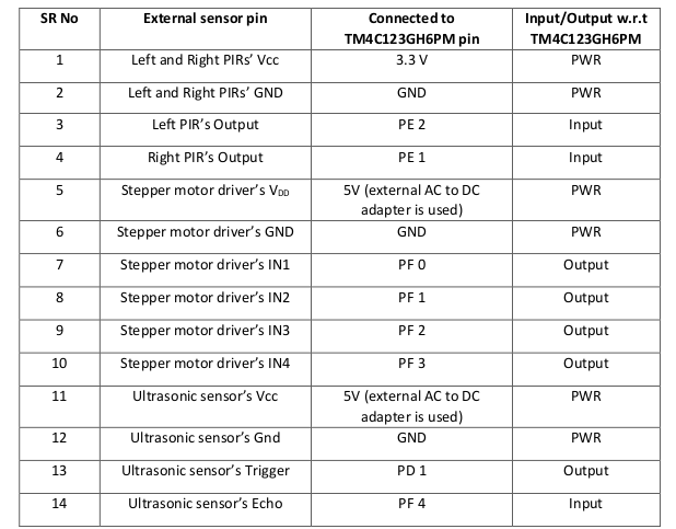
Table 1: External Sensors and their connection with TIVA Board
3.PWR
Working Principle of the system
When the left PIR sensor senses a movement, it triggers the stepper motor to move anti
clockwise by 900 to measure the distance and angle of the probable target that could have
triggered the PIR sensor.
Similarly, when the right PIR senses a movement, it triggers the stepper motor to move
clockwise 900 to measure distance and angle of the probable target that could have triggered
the PIR sensor.
The motion of the motor is restricted from -900 to 900.
When the system is serving one PIR sensor, if the other PIR sensor gets triggered then, it
is saved in a pended task list.
The system then executes the tasks which are saved in the pended task list.
The LCD display shows the angle and distance.
The Seven Segment Display shows the number of objects detected.
4.Modes of Operation
The system is designed with two modes of operation. First mode is being the Interrupt
Mode and the second one being a continuous mode.
4.1 Interrupt Mode:
In this mode, the system continuously checks for the pending tasks list. If there is no
task present, the system waits for the tasks. And, if there is only one task present, the system
serves that task and waits for the future tasks. And, if more than one tasks is pending, the system
starts serving the tasks in first come first serve fashion, and after serving all the tasks, it waits
for the future tasks.
Here, task L refers to, scanning the left side of the system i.e 00 to -900 and measuring
the angel and distance of objects.
Similarly, task R refers to, scanning the right side of the system i.e 00 to 900 and
measuring the angel and distance of objects.
And, pending tasks list consists tasks, the task being currently done and some tasks that
are pending and will be served one after the other. After serving any task, that served task is
removed from the list, and the next task is served.
If the system is currently serving a task, and meanwhile if either of the PIR sensors
detect motion, the pending tasks list is checked if that task is already pending in the list. If the
task is already there in the pending tasks list, it is ignored. And if the task is not there in the
pending tasks list, then that task is added to the pending tasks list, which will be served after
its prior tasks are served. This functionality is added to avoid the overflowing of the pending
tasks, and also there is no use of scanning it again.
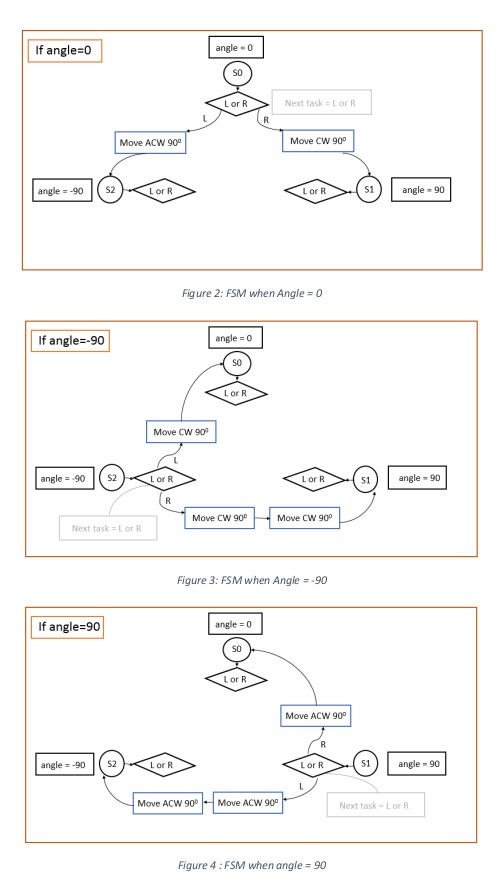
The two types of tasks task L and task R are designed based on the last task the system
has served. Suppose, if the last task done was task L (for which motor rotates anti-clockwise
from 00 to -900) the motor stops at -900. And, if the next task is also L, then the motor has to be
rotated 900 clock wise to serve the task L again. And, instead if the next task is R, then the
motor has to be rotated by 1800 to serve the task R. So, the stopping point of the motor defines
how the next task is to be done. A finite state machine is designed to, properly check the current
state of the motor and do the next task. The FSM diagrams shown below describe how the next
task is done, when the current state of the motor is 00, -900, and 900.
4.1.1 Pending Tasks List:
The 0th task in the pending tasks list, is the task being served.
The 1st task in the pending tasks list, is the next pending task, which will be served after
current task is done.
The 2nd task in the pending tasks list, is the second pending task, which will be served
after current task and the 1st task are done.
Once the current task is served, it is eliminated from the pending tasks list. The 1st task
becomes the current task or 0th task. And, the 2nd task becomes the 1st task.
How the tasks of pending tasks list are served for different cases is explained below.
Case 1:
If the pending tasks list has no tasks at all, which ever task is added first by PIR sensor
is served immediately. This task can be either L or R.
Case 2:
If the pending tasks list has only 0th task or current task, and if either of the PIR sensors
asks for a task, it is added into the pending tasks list as 1st task or next task.
Case 3:
If the pending tasks list has only 0th and 1st tasks, and if one of the PIR sensors requests
for a task, the 1st task is compared with the task asked by the PIR sensor. If both are same, the
task is not added again into the list. If both are different, then the task is added to the pending
tasks list as 2nd task.
Case 4:
If the pending tasks list has 0th, 1st and, 2nd tasks, then request from both the PIR sensor
is not added to the list. Because the 1st and 2nd tasks in the list are always different, and are
already scheduled to be done.
So, the pending tasks list doesn’t have more than 3 tasks (0th,1st and, 2nd) at any time,
i.e, no overflowing of tasks.
4.2 Continuous Mode:
In this mode, the motor continuously rotates clockwise or anti-clockwise to cover the
900 to -900 range and ultrasonic is used to measure the distance through out the range of angles.
This is a polling-based method of scan which can be used by the user of the system to scan the
surroundings before actual deployment.
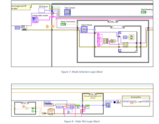
5.Selecting the Mode
The mode of operation can be selected by the user by sending the command “CONT”
or “INT” through the GUI.
6.Working of external sensors
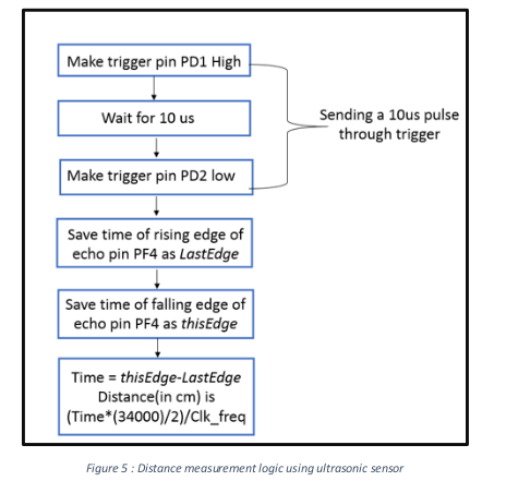
6.1 Working of Ultrasonic Sensor:
The ultrasonic sensor is used to send a pulse of 10 micro seconds (is given by the TIVA
board through trigger pin) and, the reflected pulse is captured and sent to TIVA board through
the echo pin. The time stamp when pulse is sent and the time stamp when the pulse is detected
are differenced to calculate the time taken by the pulse to hit the object and get reflected back.
This time is used to calculate the distance to the object.
6.2 Working of Stepper Motor:
The coils (1,2,3 and 4) of the stepper motor are controlled through PF0,1,2 and 3 pins
of the TIVA board. To make the motor move in clockwise direction, the following sequence isinitiated for one rotation.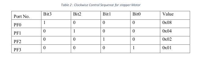
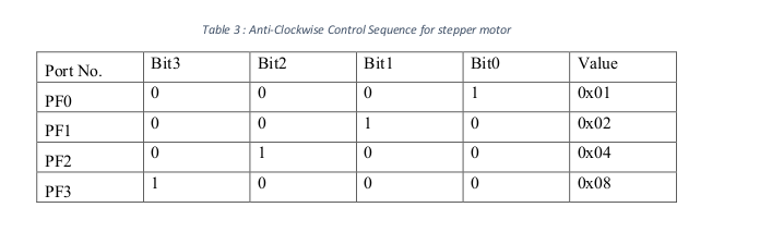
To make the motor move in anti-clockwise direction, the following sequence is initiated
for one rotation.
6.3 Working of PIR Sensor:
The output pin of the PIR sensor provides an active high pulse whenever a motion is
detected, otherwise the pin remains active low. The rising edge of the PIR output triggers an
interrupt in our system which adds the task to the pending task list.
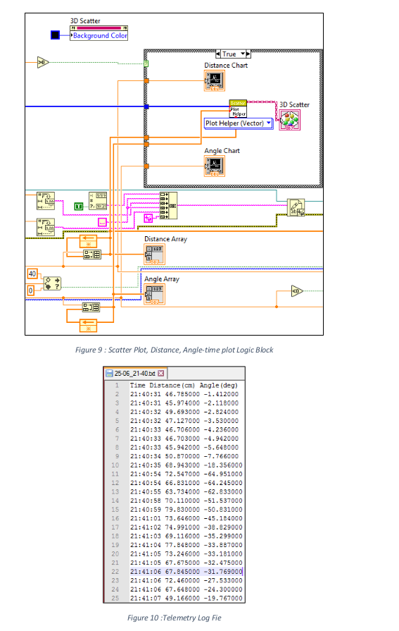
7.Graphical User Interface of the system:
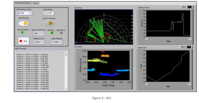
The GUI offers COM port selection and Operation mode selection (Continuous
/Interrupt Mode). The user can choose the mode of operation at any time. The GUI displays
the polar plot of the scanned area where the red highlighted portions correspond to potential
target points. The Distance chart gives information about the distance measured by the
ultrasonic sensor over time. Similarly, the Angle chart gives information about the
anglemeasured during the rotation of the stepper motor over time. The scatter plot displays the targets
as a function of distance and angle. This gives us a better idea about the coverage of the target.
The clustered points correspond to a single target.
The UART terminal shows the data received from the TIVA board during the scanning
process This string of data is processed in LABVIEW to generate the polar, scatter and time
plots.
The distance and angle values at each timestamp are derived from the UART data
received from the TIVA board and displayed on the GUI. The software also generates a
telemetry file with timestamp which can be later used by the user to analyse the data.
8.Conclusion:
An embedded system was built successfully by interfacing PIR and ultrasonic sensors
with the TM4C123GH6PM board. The robustness of the system was checked in continuous
mode and in interrupt mode by giving different sequences of interrupts continuously.
This type of embedded system can be used in in-house robot applications, where the
robot has to keep a record of how the objects are aligned in the room, and also to track the
changes in the position of the objects (a Simultaneous Localization and Mapping (SLAM)
algorithm can be built to create a mapping of objects in the room). And, this system can also
be used to identify alive targets inside inaccessible areas like small caves, excavation sites etc.
And this can also be used to detect if someone has accidently left a child/pet inside a car.
9. Link of Demo : https://www.youtube.com/watch?v=3InnDiaz_zQ
Recent Comments