
OBJECTIVE
To design a DC motor controlled robot(controlled by TI Tiva Board TM4c123gxl) that takes feedback from 3D-TOF camera and avoids collision using the depth information.
PROJECT OVERVIEW
A DC motor controlled robot that uses four GM25-370 motors is configured to work at the required frequency of PWM for the required speed of the robot.To adjust the load and speed imbalances, feedback is set from the four wheels using hall sensors available on the four different motors.Due to some of the technical reasons, we shifted from TOF camera to an IR sensor ISL29023 on the booster pack BOOSTXL-SENSHUB. We analysed the data from the IR sensor at different circumstances and avoided the collision of the robot with reference from the starting point.
CONFIGURATIONS AND SPECIFICATIONS
- 4 PWM outputs(mode0-generator 0,mode1-generator1)
- 2 Enable signals to control the direction of the rotaion(PF2,PF3)
- LIPO 12V battery
- motor drivers for GM25-370
- configuring IR sensor ISL29023 in mode-3 to get better resolution and also to reduce the effect of ambiance of IR
- supplying 5v for TIVA from the motor driver
- one switch on the TIVA used to give the command “start” for the robot and other switch to stop the robot by stopping PWM signals.
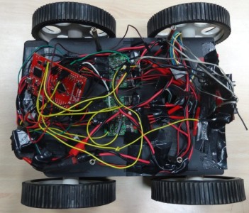
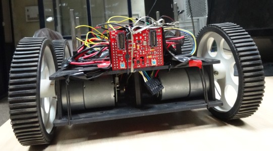
BUILDING THE ROBOT
For the maximum speed of the robot, we need to provide the maximum PWM frequency that can be generated from TIVA. We configured the PWM frequency to 1MHz for the maximum speed.By using dead band of 5%, we are ensuring the smoothness of the transitions between the wheels while they are switching. The data from the hall sensors are read which showed 45rpm based on the frequency of hall signal generated. Using the data from hall sensor’s, the frequencies of the PWM’s are adjusted to ensure the equal rotations of all the wheels for the robot to go as straight as possible.
The following commands(from uart) are used to run and control the robot motion:=
1. START :: start the generation of PWM’s for all the four motors
2. LEFT :: To turn the robot to left direction, change the direction of left motors to anti-clockwise
3. RIGHT :: To turn the robot to right direction, change the direction of right motors to anti-clockwise
4. BACKWARD :: To reverse the direction of robot motion, change both the direction pins to anti-clockwise
5. STOP :: Stop the generation of PWM’s for all the four motors to stop the robot
Since we need to make the robot independent to the uart, the switches are used to trigger the start and stop signals as follows:
Press “Switch-1” :: Start the robot in forward direction (GREEN LED glows indicating start)
Press “Switch-2” :: Stop the robot if it is in motion (RED LED glows indicating stop)
PROBLEMS ENCOUNTERED WITH TOF
Since the datasheet of the OPT8320 is available online, we thought of using the sensor module seperately and communicating using I2C or SSI. But we were unable to get the pin packaging that it supports. Later we found that the expansion port of the evaluation module supports I2C communication, we tried to communicate accordingly but the slave was not responding (no acknowledgement) due to invalid slave address. We have no information available about the register map as well as slave address. Hence, we shifted from OPT8320 to IR sensor ISL29023.
WORK DONE ON IR-SENSOR(ISL29023)
We configured the sensor in mode-3 operation which gives range up to 64,000 LUX and ADC resolution of 16-bit, which are appropriately selected for the application. The values of IR-Sensor are normalized such that they are rounded-off to the nearest precision values to decrease the noisy variations while sensing. While the robot is in motion, the sensor is giving the IR intensity values ranging from 7-90(Indoor Conditions, ambient dependent), 20-300(outdoor Conditions, ambient dependent).
ALGORITHMS IMPLEMENTED FOR COLLISION AVOIDANCE
The following algorithms are implemented in the TIVA after getting the sensor data values:::::
1. Before the robot receives the start command, we are taking a reference IR reading from the IR module. This reference value we will use throughout the motion of robot. When the robo is moving, if the IR value goes below the reference value by a degree of 10(indicates obstacle) we will stop the robot and make it move little backward to get back to the safe position.
2. When the robot is in motion, we will take the consecutive readings from the sensor and find the difference between the values received. If the difference is high, which indicates that some obstacle is there, then we will decrease the speed of the robot and give backward command to reach the safe position.
3. Once the robot is in safe position we will take 30 degree right angle turn and again take the values from the sensor. If the value received is high enough(indicates no collision), we will again give the start command to move forward. If the value is not high enough, we will take 30 degree right turn again and check the vale. This feedback values we will continuously monitor to avoid the collision of the robot with the environment.
FINAL DEMO
- YOUTUBE LINK OF FINAL DEMO – https://www.youtube.com/watch?v=7sU-BRnybhQ&feature=youtu.be
Recent Comments