
Aim of the project
The aim of the project is to construct 3D image using 3D Time Of Flight(TOF) Camera remotely.
Problem Statement
Getting 3D image using 3D TOF camera. The camera is mounted on servo motor to increase its field of view. The camera and motor are controlled remotely through WiFi.
Description
The project work is divided into two parts. The first part includes mounting the camera on the servo motor to increase its field of view and to enable control of camera from remote location. The second part is on signal processing of the raw image got from the camera. (In here Part 1 works are detailed)
Components Used
- 3D TOF Camera
- Tiva Microcontroller (tm4c123gh6pm)
- Raspberry(optional)
- Servo motor
- WiFi dongle
Main Block Diagram
Block Diagram
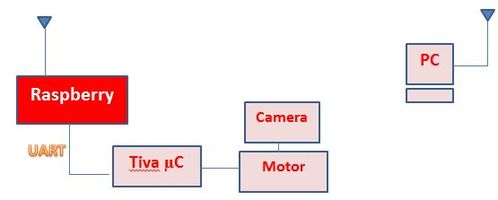
As shown in the block diagram the camera is mounted on the servo motor. This increases the field of view of camera. The camera and motor are accessed remotely using network.
Demo video
Stages
- Stage 1: Mounting of camera on servo motor and its control using Tiva Microcontroller.
- Stage 2: Getting raw image from 3D TOF Camera (done by other batch (Part II)).
- Stage 3: Control of motor and camera remotely using WiFi dongle.
Stage 1
The 3D TOF camera has small field of view. So the image captured by it is limited to smaller region. Hence complete 3D image of the object is not available. So the idea is to rotate the camera using servo motor and sweep 180 deg space both in horizontal and vertical direction.
- Servo Motor Basics
Servo Motors have error sensing feedback control. They do not give continuous motion but give precise discrete angle rotations. The amount of angular rotation is restricted to 0-180 deg (depends on the servo motor used). ‘SERVO PAN/TILT CAMERA/SENSOR MOUNT WITH 2 X MICRO SERVO 9G DIY’ servo motor (Model : RKI-2359) from Robokits is used. It has two axis platform with two micro servos (9g) as shown in figure.
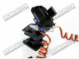
Servo motor used
- Servo Motor Connections
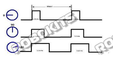
Servo motors come with three wires or leads. One is connected to +Vcc (red in colour), second is connected to GND (black in colour) and third to command pin (any colour, depends on manufacturer). DC supply voltage given is 3.3V (From Tiva board). If we see servo needs 4.8V supply but if we give 3.3V as PWM then it works fine. Unlike DC motors, reversing the ground and positive supply connections does not change the direction of rotation of a servo. This may, in fact, damage the servo motor. Hence connecting the wires properly is important.
Servo motor working
The servo motor is operated in two modes.
- 1. Continuous : The motor continuously moves 0 to 180 deg horizontally and 0 to 180 deg vertically.
- 2. Discrete : In here the user has control to set the position of the motor. X and Y angles should be mentioned and the motor rotates to the specified angles.
Stage 2
Explained in Part 2
Stage 3
Here the work is to control the motor and camera remotely. Since Tiva board (tm4c123gh6pm) doesn’t support wireless connection we have made use of raspberry board. So what is done is from PC terminal the controlling commands are sent to raspberry through SSH remotely. From Raspberry these commands are given to Tiva board through UART connection and Tiva board controls the motor. Use of Raspberry is optional. If we have USB to UART WiFi Dongle then connection can be made directly. Using Tiva, programming is done in C code to control motor.
- SSH Basics
SSH stands for Secure SHell. It was designed and created to provide the best security when accessing another computer remotely. Not only does it encrypt the session, it also provides better authentication facilities, as well as features like secure file transfer, X session forwarding, port forwarding and more so that you can increase the security of other protocols.
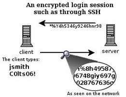
Secure Shell
Expected and Achieved
- The remote access of the motor was expected to done through WiFi but instead done through network
- The motor position was not checked for reliability
Future Scope
- Control of motor through WiFi
- Reliability check for motor
References
- http://support.suso.com/supki/SSH_Tutorial_for_Linux
- http://www.engineersgarage.com/articles/servo-motor
Team Members
- Vinishiya Reema Mendonca
- Praveen Kumar
Recent Comments