
What we have to do???
    The project aims at stabilizing a 2 wheel Robot/Car. The Car should be stable against the minor external disturbances and should be able
to maintain its balance to a great extend. The project was aimed initially  in balancing a smart car from M/s Freescale on its two rear wheels.
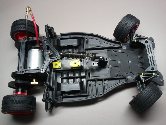
Image of smart car from Feescale (Courtsey: www.google.com)
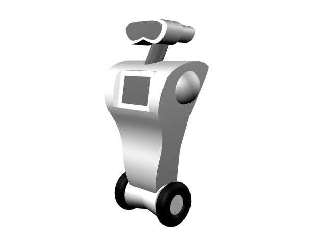
Self-balacing Robot (Courtsey: www.google.com (not ours))
What is this about???
    Self balancing structures are ideal example to prove the extend of applicability  of embedded systems, ruggedness of control systems
and an example to handle real-time systems. From the embedded context, these type of projects are helpful in providing the designer a much
better insight about RTOS (real time operating systems), FPU (Floating point units) and the digital signal processing techniques.

     Here in this project we are targeting to self balance a smart car from M/s Freescale on its two rear wheels. This is a real time sys-
tem where we have to take decision on the go. This car on it's two wheel is unstable and won't be able to stand. Here we develop motor
driving electronics(Hardware), PID control, filtering techniques and RTOS(Software) as the part of the project.
Is there any Physics over there???
Here the force which makes the system to unstable is the rotating torque in the direction of C.G (centre of gravity) shift. To compensate this we move the wheels in a direction which counter balance the torque from C.G. i.e the net torque makes the system stable at the desired angle.How we balance the system!!!!
How does control system work???
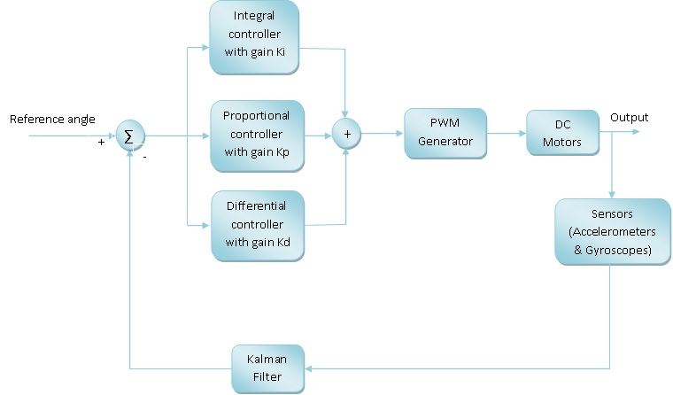
This is how we implemented Control System
Hardware Requirement
- Structure/Chasis of Car ———————————————————> 1Nos
- DC-Motor (Preferably 5A motor) ————————————————–> 2Nos
- Battery (7.2V, 1A) ————————————————————–> 1Nos
- Tiva launch pad board (for TM4C123GXL) ——————————————> 1Nos
- Sensor hub Booster pack for launch pad ——————————————> 1Nos
- Motor driver L298 Board or IC (Board is preferred) ——————————> 2Nos
- Wheels for Car ——————————————————————> 2Nos
- Switches (for ON/OFF) (We used SPDT swich) ————————————–> 1Nos
- 7805 (For generating 5V) (Procured associated capacitors also) —————–> 1Nos
- 10uF, 0.1uF capcitors —————————————————– –> 10Nos (Aprrox)
Software Requirement
- Eclipse for programming
- Open-OCD for debugging
What we tried to do!!!!
We have started with the smart car from M/s Freescale. We build a powering platform for TIVA launch pad. The platform contains the 3.3V generator for TIVA, Motor driver circuitry based on L298 IC.The image of the platform mounted on car is shown below.
Smart car ready to stand up!!!!
A simple systick based OS is implemented in the TIVA launchpad board. As a starting point we considered only the accelerometer as the sensor. We also implemented a simple PID controller. During the testing of this configuration, we found that the controller is not able to stabilize.
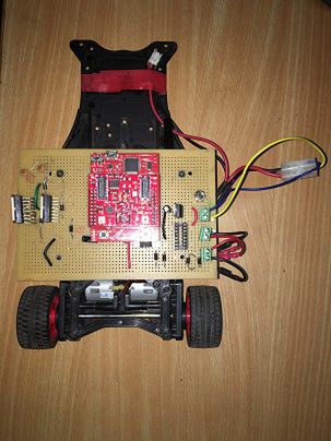
Then we have decided to change the platform to a new car (Here we doubted whether the platform is stabilizable or not). The structure of the new platform is as shown below.
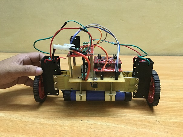
New face of project!!!!
Here we decided to go with the previous code. Then we faced the same instability issue here also. With further literature survey and consultancy with Mr Arvind (DESE), we realized some mechanical adjustments on the system has to be done. Especially on the position of battery. We also realized that accelerometer reading is not the best choice for the bodies in motion like this project. This is due to the sensor noise in the accelerometer. Hence we decided to take gyroscope data also. Here involves the the data fusion of accelerometer and gyroscope. This also calls for the filtering to reduce the noise.
The options for filtering were
- Kalman filter (KF)
Please refer the following link for better understanding of KF [1]
- Complimentary filter (CF)
Please refer the following link for better understanding of CF [2] [3]
With these modifications we felt that the system is stabilizable. After this we started tuning the gains of PID controller. The gains were tuned by following nichols ziegler method [4].
Then we found that the system is stable!!!!!!!!!!!!!!!!!!!!!.
How Software works???
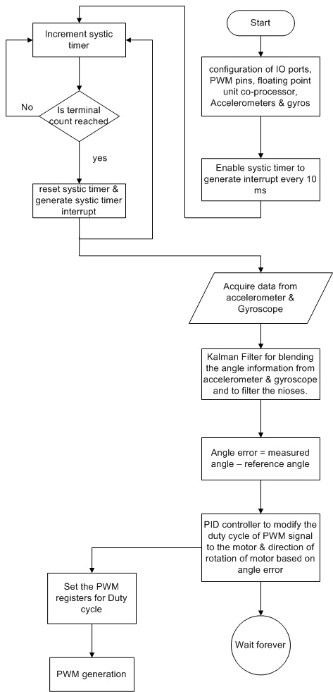
Software Flowchart
Finally this one stands!!!!!!!!!
Self Balancing Video
Immunity to External Disturbance (video)
Start from sleep (video)
Back to Smart Car
With the experience gained from the design of previous car, we tried stabilizing the Smart Car. Here we went with the previous code and with minor PID tuning, we could stabilize the Smart car. Finally the smart car stands!!!
Self Balancing Video of SMART CAR
What further can be done???
Accurate position control can be done by incorporating a rotary encoder.
Team Members
- Anil George
- Arjun N
- Aswin S M
- Lithin M G
Recent Comments