
Design requirement:
Generate sine, triangle and square wave signals of different frequency and display the signal by using Kentec QVGA Touch Screen Graphics Display and TM4C123G Evaluation kit.
Resources needed:
• TIVA C Series Microcontroller (TM4C123GH6PM).
• Kentec QVGA Touch Screen Graphics Display.
• Code Composer Studio IDE.
• GCC.
Project description:
The project generates sine wave, triangular wave and square wave of any frequency given by user enabled with touch screen. The user can interact with the touch screen display and
choose to generate any wave from the choices and can choose any frequency he wants to generate. The generated wave will be displayed on the screen with a scale of 1u sec per pixel
on x-axis and 0.01 volt per pixel on y-axis. The user can also swipe the displayed wave right and left.
Sine wave generation:
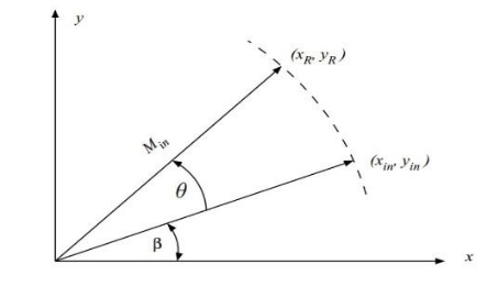
The sine wave is generated by using the cordic algorithm. CORDIC (COrdinate Rotation DIgital Computer) is a hardware efficient iterative method which uses rotations to calculate a sine and a cosine functions. Suppose that we have an efficient system that receives a vector and rotates it by an arbitrary angle θ . Choosing the origin as the centre of rotation, we will get to the point (x1, y1) by
rotating the point () by θ
xR = xin cos( θ ) – yin sin( θ )
yR = xin sin( θ ) + yin cos( θ )
if we take cos( θ ) common we will get
xR = cos( θ ) {xin – yin tan( θ )}
yR = cos( θ ) {yin + xin tan( θ )}
if xin = 1 and yin = 0, the above equations become
xR = cos( θ )
yin = sin( θ ).
if we can restrict the angles of rotation i.e., tan( θ ) = 2-i and store the θ values in a lookup table or an array. then the equations become
xR = cos( θ ) {xin – yin 2-i}
yR = cos( θ ) {yin + xin 2-i}
now the multiplication of tan( θ ) became multiplication with 2-i which is just right shift.
The algorithm rotates the coordinates anti clockwise or clockwise based on the resultant angle from the previous iteration.
X[j+1] = {X[j] – σj Y[j] 2-i}
Y[j+1] = {Y[j] + σj X[j] 2-i}
Z[j+1] = Z[j] – σj itan(j)
Z is the resultant angle from the previous state.
Based on the sign of the resultant angle the direction of rotation changes. If sign is positive, the next rotation will be anti-clockwise direction (σi = 1),
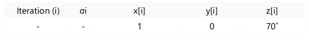
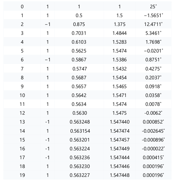
If sign is negative, the next rotation will be clockwise direction (σi = -1). The first in cordic is the pre-rotation which will bring the phase in the range of 0˚ and 360˚. The table below shows the calculation of the sin(70˚) and cos(70˚) with iterations.
Iteration
In the above equations we are not involving the common factor of cos( θ ).
The cos( θj ) will be same for anti-clockwise and clockwise rotations because cos is an even
function.
So, the cos( θ0 ). cos( θ1 )….. cos( θ19 ) tends to 0.6072.
So we have to multiply this with X[20] and Y[20] to get correct values of sin and cos.
sin(70˚) = 1.547448 * 0.6072 = 0.93961
cos(70˚) = 0.563227 * 0.6072 = 0.3419
Triangle wave generation:
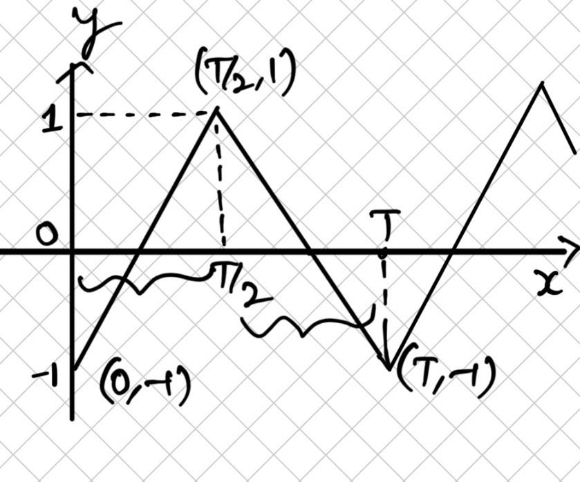
The equation for the first half wave is
Y = (4/T) *(X) – 1
And equation for second half wave is
Y = -(4/T) *(X – T) – 1
Where T is the fundamental time period of the wave.
Graphics LCD interfacing:
Introduction:
The BOOSTXL-K350QVG-S1 Kentec QVGA Display BoosterPack is an easy-to-use plug-in module with a touch-screen color display.We can use this BoosterPack to start developing
applications using the 320×240-pixel TFT QVGA display with resistive touch screen. It uses SPI for communication.
Key Features:
1. Kentec TFT LCD (part number: K350QVG-V2-F)
3.5-inch QVGA (320×240 resolution)
SPI communication
4-wire resistive touch screen
White LED backlight
2. LED backlight driver circuitEMBEDDED MINI PROJECT REPORT
3. Complies with the BoosterPack standard for use with 20- and 40-pin LaunchPads.
BOOSTXL-K350QVG-S1 Interface control.
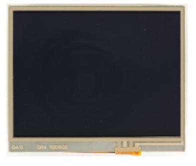
The following figure is the graphics display (BOOSTXL-K350QVG-S1)
From the following figure of the tiva c series launchpad we have to remove the Register R10 for the interfacing of graphics display.EMBEDDED MINI PROJECT REPORT
Implementation:
First, the user will choose the type of wave he wants to generate by touching on the widget. After that, the user have to give the frequency by touching plus and minus buttons on the
screen and then touch generate widget on the screen. Then the generated wave will be displayed and there will be three buttons on the screen named back, R and L.
Back button will take you to the first screen and the R and L buttons are used for moving the wave right and left as we do in an oscilloscope.
Problems faced:
While clearing the screen the widgets added previously will not be removed. They will still be there but not visible. So, we have to remove the widgets manually.
We have to make sure that the data of the wave must be with in limits of the memory on the launchpad. If the data generated is larger than available memory on the launchpad, it will
give us error.
Future scope:
This signal generator can be used to generate sampled sine wave signal. So, it will be useful in many applications of communication systems and digital signal processing systems.
This can be also used in finding the electrical properties of a human tissue in micro biological systems.
References:
TivaWare™ Peripheral Driver Library (User Guide) .
BoosterPack (BOOSTXL- K350QVG-S1)
Team members:
P. Sai Surya Srinivas
J. Nischala
Recent Comments