
This page describes the Heart Rate Monitor with Bluetooth Interface project, which is a part of the Embedded Systems-1 course. The aim of this project is to build a Digital Heart Rate Monitor which uses a graphical LCD for displaying the pulses and a BLE-113 module for transmitting the calculated heart rate to bluetooth device.
Introduction
This project implements a Digital Heart Rate Monitor with a Bluetooth interface. It involves amplifying the desired weak signal in the presence of noise from power supply and electromagnetic interference. The amplified signal is then digitised using the STM32L152RBT6 and the digitised signal is then displayed on a JHD12864E graphical LCD. From the obtained signal, heart rate is calculated using an algorithm. This heart rate is then transmitted using BLE113 module and displayed on PC using BLE Device Monitor.
Theory
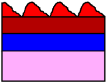
Light Absorption Diagram
The figure on the right shows the absorption of light. The DC components are due to tissue(light has to pass through tissues before it reaches the arteries), venous blood, and non-pulsatile arterial blood. The AC component is due to pulsatile arterial blood. The AC signal is of importance when measuring the heart rate.
Design and Algorithm
Custom Sensor Board Design
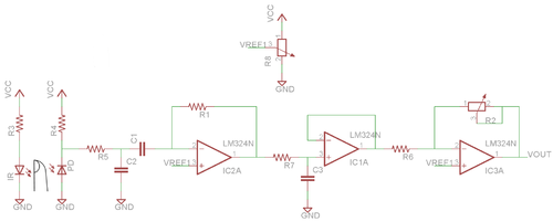
Sensor Board
Digital Board Design
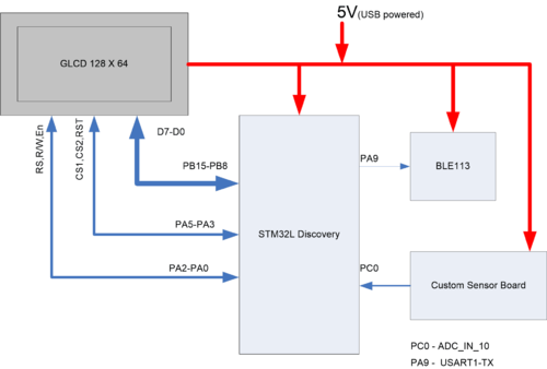
Digital Board
The digital board contains the STM32L152RBT6 controller interfaced to
- the sensor board using the inbuilt ADC
- the BLE-113 module using the inbuilt USART
- the graphical LCD JHD12864E module using GPIO pins.
The inbuilt ADC samples the data at the rate of 64 samples per second. When 128 such samples are accumulated, the heart rate is calculated using an algorithm mentioned ahead. The 128 samples are also sent to be displayed on the graphical LCD. The calculated heart rate is sent to the via the transmit pin of the UART to the BLE-113 module. This module is programmed to send the data via bluetooth.
Sensor Board Interface
Pin PC0 (ADC channel 10) is configured as the analog input pin. The ADC is configured to a resolution of 12 bits. Single Conversion mode of the ADC is used. The sampling time is set to 192 clock cycles.
BLE-113 module Interface
Pin PA9 (USART1 Tx) is configured to be the transmit pin of USART. Data is sent serially on this pin to the BLE module to be transmitted. The 8051 microcontroller inside the module is configured to send this data via CC3000.
Graphical LCD JHD12864E Interface
The graphical LCD primarily needs 8 data lines, 2 chip select lines(to select which 64*64 section to display data to), an instruction/data line, a read/write line and a reset line from the microcontroller. The reset line is used to clear the LCD. Then by proper configuration of the lines, the data can be written to the one of the two 64*64 sections of the LCD. Contrast can be adjusted by varying the potentiometer connected to the LCD.
BLE-113 Configuration
The BLE-113 implements a Bluetooth SIG standardized Heart Rate Sensor profile.
The Heart Rate Profile contains three services:
- Generic Access Profile (GAP) service
- Device Information Service (DIS)
- Heart Rate Service (HRS)
1. Generic Access Profile service Every Bluetooth low energy device needs to implement a GAP service.The service has two characteristics,
- Device name
- Appearance
2. Device Information Service This is a mandatory service the which must be implemented for this profile. This service exposes information about the manufacturer of the device and optionally other information about the device, like device model number and software version.
3. Heart Rate Service This service implements one characteristic, Heart Rate Measurement. This service causes the broadcast of heart rate information to take place whenever new heart rate data is available. The Device is programmed using a CC-Debugger and BLE Software Update Tool from Bluegiga.
Power Supply Design
The entire circuit is USB powered.
Algorithm
After initialising the circuit using software, the microcontroller enters a section of code that is described briefly in the below algorithm.
0.  Set ''limmax'' and ''limmin'' for hysteris action.
1.  Call ADC every 7.5ms.
2.  Collect 128 samples and display on Graphical LCD.
3.  Start from first sample.
4.  Wait for ''limmax'' rising crossing. Store index of sample of ''limmax'' crossing.
5.  Wait for ''limmin'' falling crossing.
6.  If 128 samples not covered, go to 4.
7.  Find difference between successive sample indices of ''limmax'' crossing.
8.  Find average of these differences.
9.  Multiply it by time period of sampling.
10. Reciprocate it to get Heart Rate.
11. Multiply it by 60.
12. Send result to BLE113 module for Bluetooth transmission.
Problems Faced
The pulse signal being measured is in the order of 2mVp-p. The supply for both custom sensor board and BLE-113 was taken initially from STM32L Discovery board. Due to this,noise was injected to the supply of sensor board by BLE-113, causing false pulse detection and thereby giving erroneous heart rate values. This problem was solved by using separate sources for custom sensor board and BLE-113 board.
Future Work
The project can be extended to determine Pulse Oxygen Saturation (SPO2) in addition to heart rate by adding a RED LED in addition to the IR LED and replacing IR detector with a photo diode in the existing sensor board.
Project Images
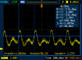
Output of Sensor Board
References
http://www.st.com/st-web-ui/static/active/en/resource/technical/document/datasheet/CD00277537.pdf
http://www.geeetech.com/wiki/index.php/Graphic_LCD_128x64_STN_LED
Source Code
The source code can be found on moodle.
Project Team
1. Karthik B. S. 2. Yogesh Palkar
Recent Comments