
Introduction
This project aims to look into the aspect of reading and writing to a file in a FAT16/FAT32 memory system.
Hardware and Software Resources Used
- Development Board based on the ARM Cortex-M3 processor.
- SD card and Audio Codec interface board details
- Hex Editor Software to view the contents on SD card.
- Eclipse and OpenOCD details.
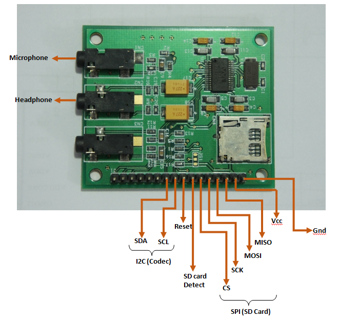
Interfacing Board with SD card and Audio Codec board
The pin connection for the Audio Codec board is as shown in the figure.
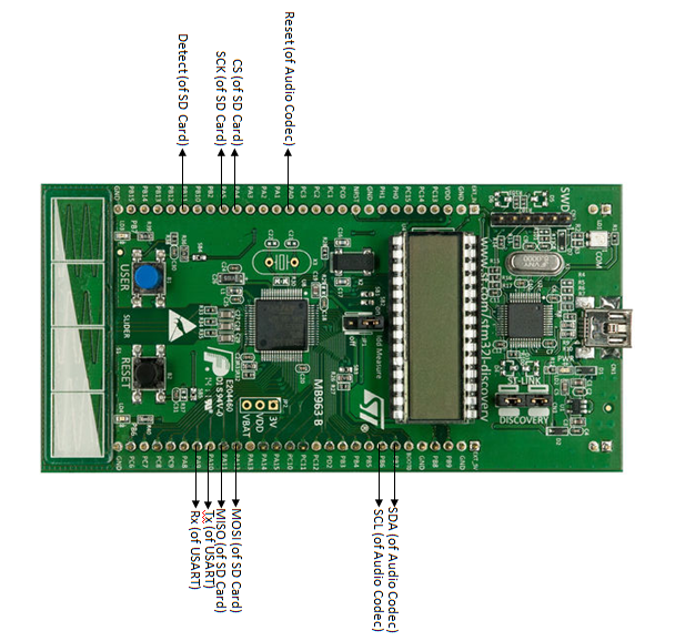
The pin connection of stm32 discovery board is
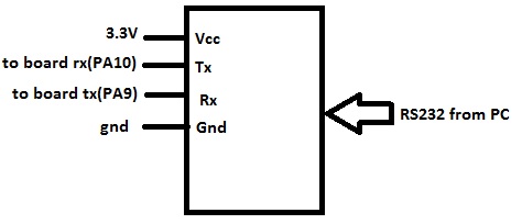
The pin connection of UART module
SD card Driver
SD card driver consist of following function
1.SD_Init()- This is for initialization of SD card to work in SPI mode at a particular speed.
2.ReadBlock(RxBuffer,Sector_Address, BlockSize)- For reading a sector at Sector_Address of given BlockSize from SD card in RxBuffer(RAM of STM32L).
1>Preparing SD Card for Reading
This involves the creation of a valid boot-sector in the microSD and over-writing all other locations with ‘0’s (or ‘1’s). The formatting process creates a sector (Ideally, Sector 0) with the appropriate settings that stores information like ‘sector size’, ‘no of FAT s’ etc. We use a sector size of 512 bytes along with 2 FATs (both are copies of each other).
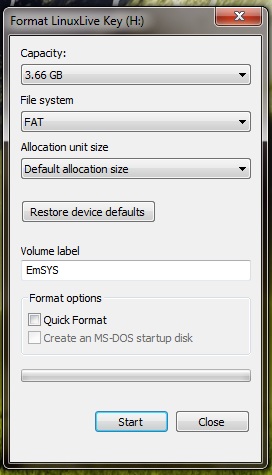
Plug in the micro SD into an adapter or an appropriate dongle (photon+, micromax etc) and plug in the device to your PC. Wait for your PC to detect the SD card. Now format the SD card (use the default FAT settings on Windows or the ‘disk utility’ on Ubuntu. Also note that it is better to disable the ‘Quick Format‘ option on Windows and click on the overwrite everything with ‘0’s option on Disk Utility as these can create problems when the project in carried out over and over again).
Now open the image of the SD card using a Hex Editor (like the HxD Editor). Find the string ‘FAT16’ or ‘FAT32’ on the Hex Editor and note the sector number (Ctrl+F and type ‘FAT16’ and press Enter). This is the ‘boot sector’. As shown in the figure
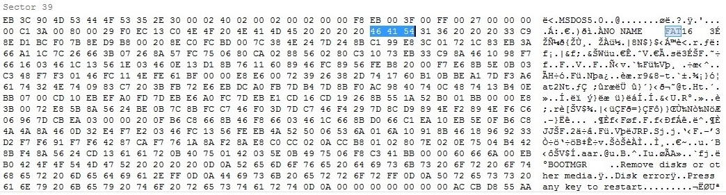
This sector number is supposed to be zero according to available documents. However, it was found that there always existed an offset between the actual boot sector and sector zero (more info at this). In our case, when we wrote a sector and tried to read it using Hex-Editor, the offset was found to be 0x7E00. To know what the sector size of the FAT is – Look into the 0x0b and the next location and note the two values ‘a’ and ‘b’ respectively. Assembling this as ‘ba’ will give the sector size. Note that this is usually 512 (decimal) i.e, the data at 0x0b is ‘00’ and 0x0c is ‘02’. Also note that 0x10 will store the number of FATs on the SD. This is usually ‘2’. This is all the information we will be needing from the boot sector for now.
2>Reading from a file
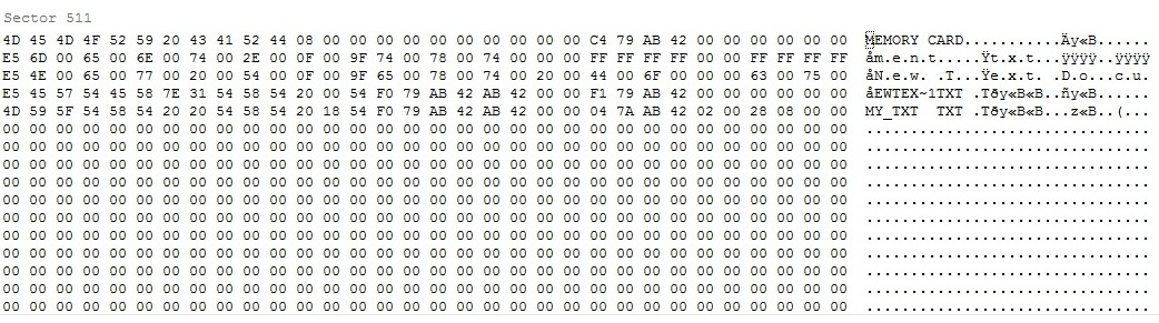
This involves creating a file, finding the sectors containing the contents of the file and finally reading the necessary sectors. After formatting the microSD create a file named ‘my_file.txt’. Any type of file( jpegs mpegs) can be created. We choose the ‘.txt’ file owing to its simplicity in editing it. In addition changes in text files can be viewed easily in both Hex Editors and the GTKTerm hyperterminal. The name of the file will be written in FAT table as shown
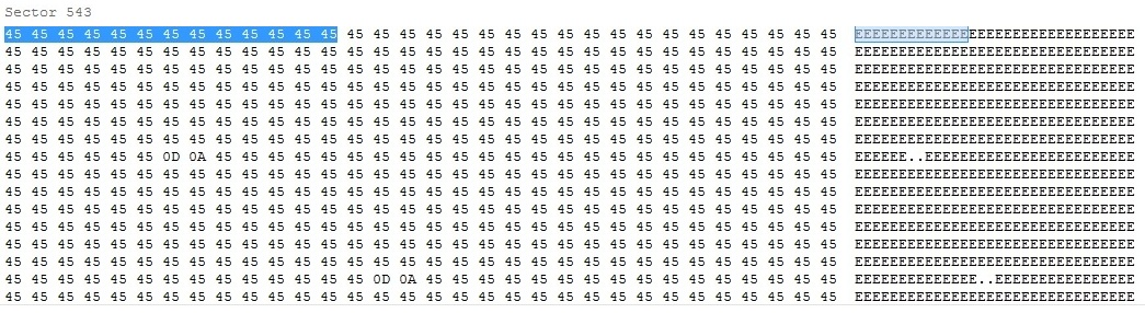
 Open the file and edit it as shown – (Any random characters can be typed in as long as the pattern can be remembered easily). Now open the image of the microSD using the HxD Hex Editor. Find the sequence of characters in the file (Ctrl+F and type ‘EEEEEE’ and press Enter). Note the sector number where the sequence of characters begin.
Plug out the SD card from the adapter/dongle and plug it into the slot on the storage board. Now use the ‘ReadBlock’ function in the main() of our existing project. Also use command ‘Print(char)’ to display value of RxBuffer after reading. The RxBuffer must be of a size greater than or equal to the no of characters in the file/sector.Save and Run the code and open the ‘gtkterm’ interface to view the characters being read. The sequence shown on the gtkterm must be the same as the sequence written to the file earlier. Note that the procedure to find the location of the contents of the file was done manually using the hex editor. This can be automated if the File Allocation table can be found and the file-name can be found in it. Here, we should take precaution to give reading address as starting address of any sector, otherwise the read will not be successful. Moreover, the BlockSize to be read should be minimum 1 sector size. ReadBlock function returns a value specifying if the read was successful. If the returned value is 0, then the read is successful.
It should be noted that for our code to run successfully on STM32L discovery board, the size of SD card should be less than or equal to 1GB.
Audio Codec Driver
I2C communication is done using following functions
1.I2CInit()-For initialization.
2.WriteRegister(Register address, Data)-For writing to Control Registers.
2.Codec_Init()-For Configuring Codec in Playback mode.
1>Initializing I2C bus
STM32L board acts as a master to initiate communication between the Audio codec board and itself. Each entity in I2C communication has a unique address. These addresses are predefined for different modules. The detailed discussion of slave address selection for WM8731 is given on page number 43 of its datasheet. In the present addon board, CSB pin is grounded and as a result, for writing to the codec, we use Slave address 0x34. Own address is chosen as 0x33. It is to be noted that WM8731 is write only and cannot be read after writing the registers.
2>Writing to Registers
There are total 11 registers (R0-R9 and RF) each containing 9 Bits of Data. This data controls power supply and filter on-off positions for input and output of Codec. They also store data for volume control such that left channel and right channel volume can be independently controlled. Also Codec has to be set in its Slave mode or Master mode which is configured by writing to these registers.
The register address uses only 7 bits to select the register, while as we already saw, each register holds 9 bit of data. As the I2C protocol will send 8 bits each time, we break this into 7+9=8+8. Thus while using write register, the first 8 bit address has [Address(6 downto 0)+Data(8)] , this is sent first to the slave module. When it is acknowledged, second 8 bit packet of [Data(7 downto 0)] is sent. Thus all 11 registers can be written by using the same method.
3>Configuring the Codec
The following table shows register values for configuring Codec in Bypass mode so as if we speak in the microphone, the voice can be heard using headphone.
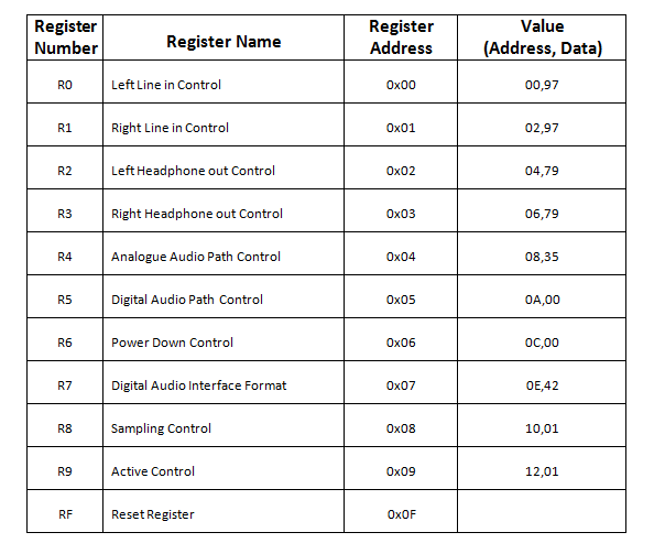
- First two registers are used to configure volume with respect to line in. But as in our add-on board, the Line in is not supported, we can choose arbitrary values for these registers.
- Registers R2 and R3 set up the headphone volume and we keep it to the maximum value of binary ‘11111’.
- Analogue Audio path controller register R4 enables Microphone and DAC and selects Bypass mode wherein input to the ADC directly goes to DAC. Sidetone is enabled.
- R5 register selects filters for ADC and disables soft-mute for DAC.
- First, in the Codec_init code, this register R6 keeps DAC in power-down mode so that during configuration, we do not hear unwanted noise. Only after the Codec is fully configured, do we enable the DAC by releasing it from power-down mode.
- Here, in R7 register, we make the Codec Master for producing Clock of its own while playing Audio. Moreover, the data Bit length is set to 16 bits. It is conveyed that data input will be in I2S format at DAC.
- We have selected USB mode in register R8 and sampling frequency is 12Mhz/250 ~ 48kHz.
- At the end of selection of all the values for configuration, we activate the Codec before releasing DAC from power-down mode by setting last bit of R9 register as 1.
Issues with I2S implementation
We attempted to Play out the stored data .wav file from SD Card on the Audio Codec Board, but realized that STM32L Discovery Board does not support I2S protocol as mentioned on pg no. 671 of *STM32L151xx, STM32L152xx and STM32L162xx — Reference Manual that in medium-density devices, the I2S protocol is not available. STM32L discovery board has STM32L152xx microcontroller which is a medium density device where the Flash memory density ranges between 64 and 128 Kbytes. Thus we switch to DAC of the discovery board to play out the music.
Playing Audio from DAC of STM32L Discovery Board
1>DAC Configuration
- Pin A5 of STM32L Discovery Board is used as DAC output.
- Timer is initialised such that it will trigger the DAC to give sample rate of 8K Samples per second. This is done by setting the TIM_Period to 0xEA, TIM_Prescalar to 0x08, TIM_ClockDivision to 0x00 and mode to be upcounting. The sample rate can be checked by giving squarewave data to the DAC as given in the code by Sqbit array.
- DAC_Trigger is set to the timer interrupt. DAC is not in the Wavegeneration mode and its output buffer is enabled. DAC Channel 2 is selected to play out the mono data from single channel.
- It should be noted that DAC input should be 12 bit unsigned nuber, so if the data is not stored in this format in the SD Card, required modifications should be done prior to sending it out on the DAC.
2>DMA Configuration
- DMA1 Channel 3 is used to take data from the address where data is stored in RAm to the DAC output buffer.
- The data size is set to 16 bits and total buffer size of 256 as there is 512 bytes data available.
- DMA in normal mode so that after it has completed 512 bytes of data, it will give an interrupt. Interrupt service routine should change the input address in RAM so that next data can be streamed.
- We have used two buffers in RAM which read from the SD Card only when they get empty.Thus the DMA address has to be changed in Ping Pong Fashion.
- For higher sampling rates, we might need to use more than two buffers, thus the number of buffers is kept flexible,this should be increased to support 48k Hz sampling rate, otherwise it will result in a lag making the output sound undecipherable.
3>Data Modification
- In order to play the file, data should be in little endian format, so if the data is in Big Endian, it should first be converted to little endian by swapping higher byte with lower byte.
- All the wav files contain signed data, which is converted to unsigned data details of which can be understood by looking at the following code.
if ( Buffer_Block_Rx[i][j]>0X7FFF)
Buffer_Block_Rx[i][j] = Buffer_Block_Rx[i][j]-0X8000;
else
Buffer_Block_Rx[i][j] = Buffer_Block_Rx[i][j]+0X8000;
- It should be noted that we are playing only 12 bit data here, but the wav file used has 16 bit data. Thus we truncate the 4 LSBs by right shifting to get 12 bit from 16 bit.
Future Works
1. Fat File System can be implemented to access files using their name and continue reading as the file proceeds in discontinuous sectors.
2. Playing the .wav file taken from SD-Card through I2S Interface using DMA channel of board having I2S capability (Olimex STM32LCD Board or STM32F4 Discovery Board) and Audio Codec Board.
References
1.[1] Open source library for further development
2.[2] Stm32l examples
3.[3] SPI+SD+FAT on 8051 example
6.Application NoteSTM32L152D board using audio codec
Project Team Members
Karisma Khatua (10310) karisma.khatua@gmail.com
Khayali Jain (10211) khayali.jain@gmail.com
Recent Comments