
Project Overview
1. The essence of project revolves around asynchronously transmitting current GPS coordinates from all networked devices, reception of GPS coordinates sent by other devices and calculation of route, crow fly distance and tentative time required for each device to reach any other device from own and received data. The route and distance calculation involve use of GPS while tentative time would require instantaneous speed given by accelerometer and distance from previous calculation. On ground route between devices could also be extracted from Google earth / Google map and transmitted to devices requesting for it.
Definition of the Problem
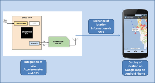
2. Integration of a GSM development board and STM LCD Olimex board with integrated GPS and accelerometer needs to be done to assort a device having functionality of a mobile (Call it Assorted Mobile). The other side of communication channel would be essentially an Android phone. GPS data from assorted mobile would be displayed on the LCD and would also be sent to all other devices registered for receiving SMS. Android phone would also extract the GPS coordinated from on board GPS and display them on screen. The Android phone as well as the assorted phone would receive the GPS coordinates of other stations and would calculate route to them and then display same on their own screen. Any change in location of either of the devices would lead to instantaneous updation of location information displayed at either ends. The displays would also show speed and tentative time to reach other end. The Assorted Mobile and Android Mobile would have been programmed earlier to receive and initiate voice calls, and send SMS.
Objectives
3. Objectives have been enumerated below:-
- Integration of STM LCD Olimex Board, GSM development board, GPS and Accelerometer.
- Android programming on Android phone to display GPS coordinates and extract data from SMS received.
- Logic programming on STM board and Android Mobile for following:-
-
- Extraction of data at both mobile devices and calculation of route.
- Display updated location information on either device.
- Indication of crossing limit for child safety.
- GUI. GUI would be created on either devices to facilitate following:-
- Display of GPS coordinates and route information.
- Suitable screen for showing map.
- Application screen giving tabs for accessing all functionalities to include calling, SMS, display of location information and a map screen.
- Aim Plus.
- Display of GPS coordinates and possibly route between location of Android phone and Assorted phone on Google Map by embedding Google Maps in own application.
- Instantaneous updation of route on Google map.
- Extraction of location data from Google Map or Google Earth on Android Mobile and displaying it on Assorted Mobile.
Theory and Algorithm
4. GPS Data.
- The National Marine Electronics Association (NMEA) has developed a specification that defines the interface between various pieces of hardware. GPS receiver communication is defined within this specification. Most computer programs that provide real time position information understand and expect data to be in NMEA format. This data includes the complete PVT (position, velocity, time) solution computed by the GPS receiver. The idea of NMEA is to send a line of data called a sentence that is totally self contained and independent from other sentences. There are standard sentences for each device category and there is also the ability to define proprietary sentences for use by the individual company. All of the standard sentences have a two letter prefix that defines the device that uses that sentence type. (For gps receivers the prefix is GP.) which is followed by a three letter sequence that defines the sentence contents. In addition NMEA permits hardware manufactures to define their own proprietary sentences for whatever purpose they see fit. All proprietary sentences begin with the letter P and are followed with 3 letters that identifies the manufacturer controlling that sentence. For example a Garmin sentence would start with PGRM and Magellan would begin with PMGN.
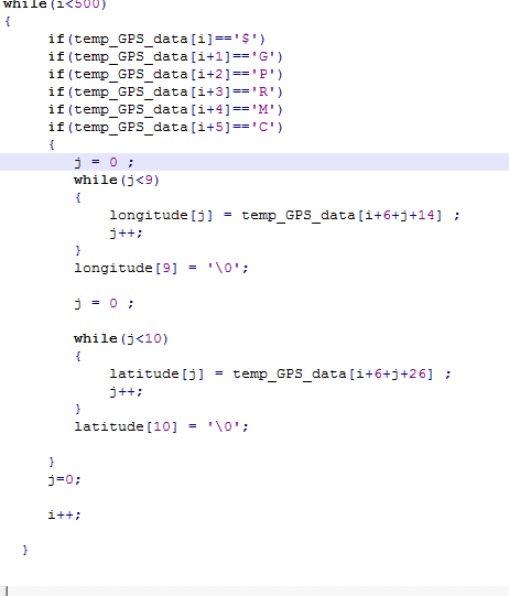
- Each sentence begins with a ‘$’ and ends with a carriage return/line feed sequence and can be no longer than 80 characters of visible text (plus the line terminators). The data is contained within this single line with data items separated by commas. The data itself is just ascii text and may extend over multiple sentences in certain specialized instances but is normally fully contained in one variable length sentence. The data may vary in the amount of precision contained in the message. For example time might be indicated to decimal parts of a second or location may be show with 3 or even 4 digits after the decimal point. Programs that read the data should only use the commas to determine the field boundaries and not depend on column positions. There is a provision for a checksum at the end of each sentence which may or may not be checked by the unit that reads the data. The checksum field consists of a ‘*’ and two hex digits representing an 8 bit exclusive OR of all characters between, but not including, the ‘$’ and ‘*’. A checksum is required on some sentences.
- Sample GPS data received has been shown below:-
$GPRMC,183729,A,3907.356,N,12102.482,W,000.0,360.0,080301,015.5,E*6F $GPRMB,A,,,,,,,,,,,,V*71 $GPGGA,183730,3907.356,N,12102.482,W,1,05,1.6,646.4,M,-24.1,M,,*75 $GPGSA,A,3,02,,,07,,09,24,26,,,,,1.6,1.6,1.0*3D $GPGSV,2,1,08,02,43,088,38,04,42,145,00,05,11,291,00,07,60,043,35*71 $GPGSV,2,2,08,08,02,145,00,09,46,303,47,24,16,178,32,26,18,231,43*77 $PGRME,22.0,M,52.9,M,51.0,M*14 $GPGLL,3907.360,N,12102.481,W,183730,A*33 $PGRMZ,2062,f,3*2D $PGRMM,WGS 84*06 $GPBOD,,T,,M,,*47 $GPRTE,1,1,c,0*07 $GPRMC,183731,A,3907.482,N,12102.436,W,000.0,360.0,080301,015.5,E*67 $GPRMB,A,,,,,,,,,,,,V*71
- This GPS data is extracted using code as shown below:-
GSM Module
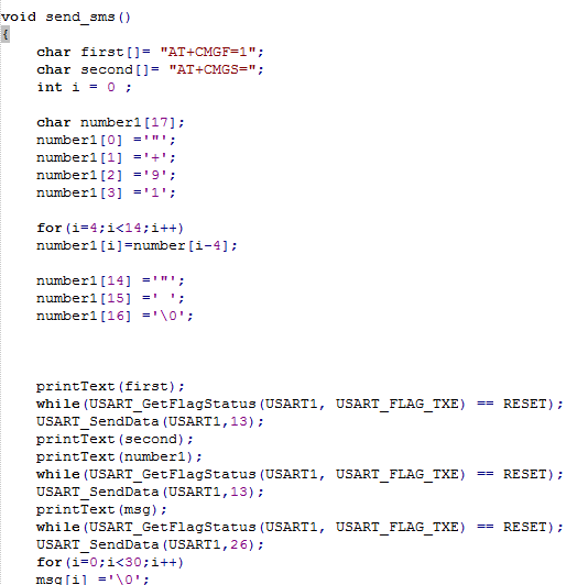
5. GSM Module has been used for voice calling and sending SMS using AT commands sent by Olimex board to GSM module connected at USART 1. Some sample AT commands ar shown below:- You want to use your computer / PC to retrieve all inbound SMS messages that have not been read before. In this case, you should use the +CMGL AT command. In SMS text mode, the command line to be used should be:
AT+CMGL=”REC UNREAD”
The GSM/GPRS modem or mobile phone should return something like this:
+CMGL: 1,”REC UNREAD”,”+85291234567″,,”07/02/18,00:05:10+32″ Reading text messages is easy. +CMGL: 2,”REC UNREAD”,”+85291234567″,,”07/02/18,00:07:22+32″ A simple demo of SMS text messaging.
OK
The +CMGL AT command can also be used to read all SMS messages stored in the message storage area. To do so in SMS text mode, the command line should be:
AT+CMGL=”ALL”
This time the response of the GSM/GPRS modem or mobile phone should be something like this:
+CMGL: 1,”REC READ”,”+85291234567″,,”07/02/18,00:05:10+32″ Reading text messages is easy. +CMGL: 2,”REC READ”,”+85291234567″,,”07/02/18,00:07:22+32″ A simple demo of SMS text messaging. +CMGL: 3,”REC READ”,”+85291234567″,,”07/02/18,00:12:05+32″ Hello, welcome to our SMS tutorial.
OK
- Sample Code for Sending SMS has been shown below:-
STM32-LCD Development Board by OLIMEX
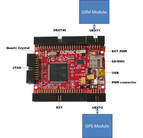
6. STM32-LCD is development prototype board with STM32F103ZE microcontroller from STMicroelectronics. This powerful microcontroller supports various serial interfaces such as USB, USART, SPI. In addition you will find also accelerometer, JTAG, TFT LCD, mini SD/MMC card connector on this board and most of the GPIOs are on extension headers where you can connect your additional circuits. All this allows you to build a diversity of powerful applications to be used in a wide range of situations.
7. Microcontroller – STM32F103ZE – high-performance ARM® Cortex™-M3 32-bit RISC core operating at a 72 MHz frequency, high-speed embedded memories (Flash memory – 512 Kbytes and SRAM – 64 Kbytes), and an extensive range of enhanced I/Os and peripherals connected to two APB buses.
GSM modem SIM-300
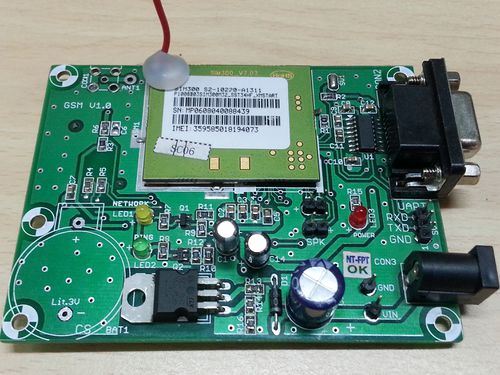
8. As shown in fig. the GSM modem used has a SIM-300 chip by SIMCom Wireless Solutions. Also this module has a UART & RS232 both to connect it to the system. It draws power from a 12V DC adapter. Olimex STM32 LCD Development Board
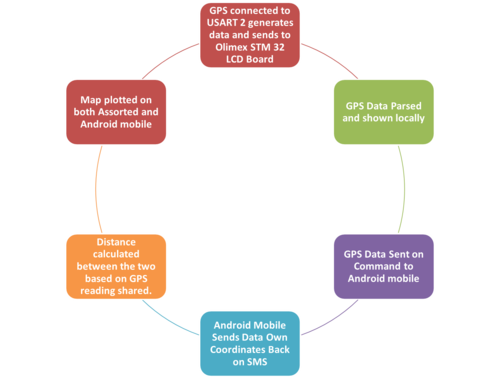
9. The LCD32 STM Board is used for overall coordination. The GPS readings are taken at USART2, parsed and sent from USART1 on to GSM module for further transmission on to other mobile. Flow of information is shown in the diagram below:-
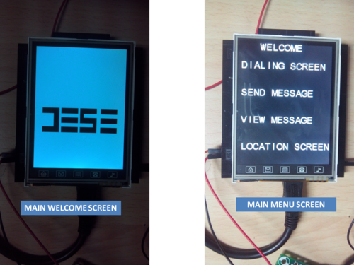
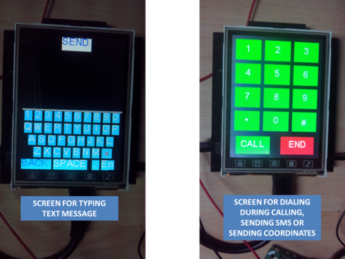
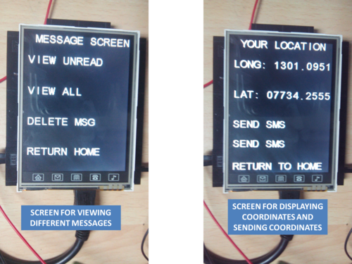
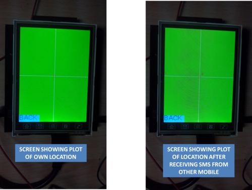
10. The various screens created are shown below:-
References
11. STM32-LCD Development Board User Manual, 2011, Olimex ltd.
SIM-300 AT Commands Set , 2006, SIMCOM ltd.
Project Team
- Sandeep Rana (rana091@gmail.com)
- Hemant Madhewar(hpmaddy@gmail.com)
Recent Comments