
INTRODUCTION
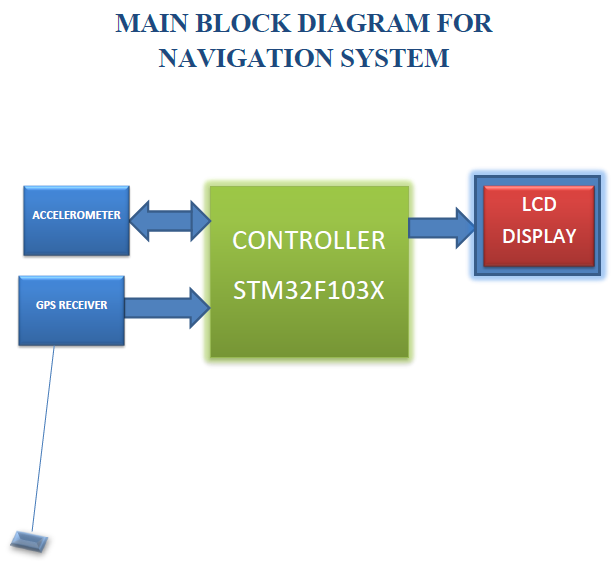
This is a navigation system using GPS, 3 – axis accelerometer LIS3LV02DL,The high-performance STM32F103ZE ARM® CortexTM-M3 32-bit RISC core operating at a 72 MHz frequency is used as main controller.Potential applications for this kind of algorithms are personal navigation, indore localization, car navigation, back-up GPS, anti-theft devices, map tracking, 3-D gaming, PC mouse, plus many others.The algorithm described in this document is useful in situations where displacement precision is not extremely critical.
THEORY AND ALGORITHM
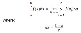
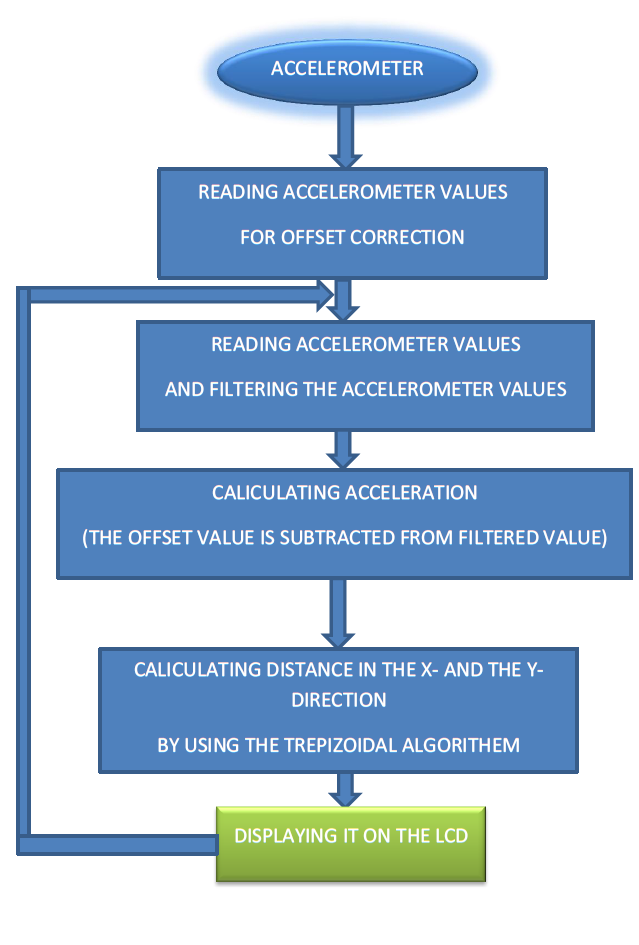
accelerometer gives acceleration in X-direction, Y- direction, and Z- direction, if we integrate them separately we will get velocity in the respective direction, if integrate velocities we will get distance in the respective direction,
                                    a = dv/dt and v = ds/dt
                                 so a  = d(ds)/dt2
                                    v = ∫a dt and
                                    s = ∫(∫a dt)dt.
This accelerometer is a Integration is the area under the curve. It can be approximated to the sum of the very small areas whose width is tending to zero.
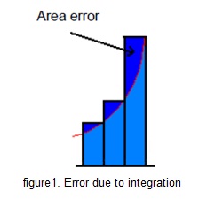
but this approach results in the area error, which keep on accumulating for the time the process is active. This area error is reduced by the first order approximation so called Trapezodial Method.
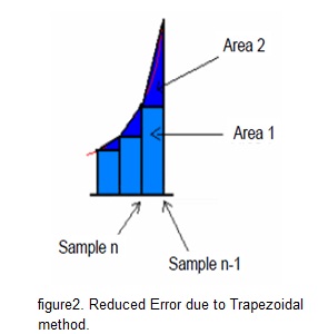
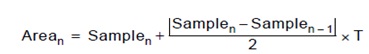
The first area is the value of the previous sample (a square). The second area is a triangle, formed between the previous sample (sample n-1) and the actual sample (sample n) divided by two.
SOFTWARE DESIGN CONSIDERATION
For real time implementation of the algorithm, the following steps are used:
1. Data sensed by accelerometer is noisy. So averaging filter is used
2. Even with the previous filtering some data can be erroneous due to the mechanical noise, so another filter is implemented. Depending on the number of samples used for filtering, a window of real acceleration is selected.
3. Calibration is done to remove the acceleration offset.
4. Actual acceleration value is the sample minus the calibrated value.
5. Time between the acceleration samples must be same otherwise error is generated.
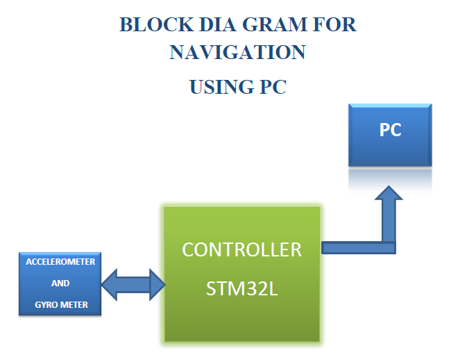
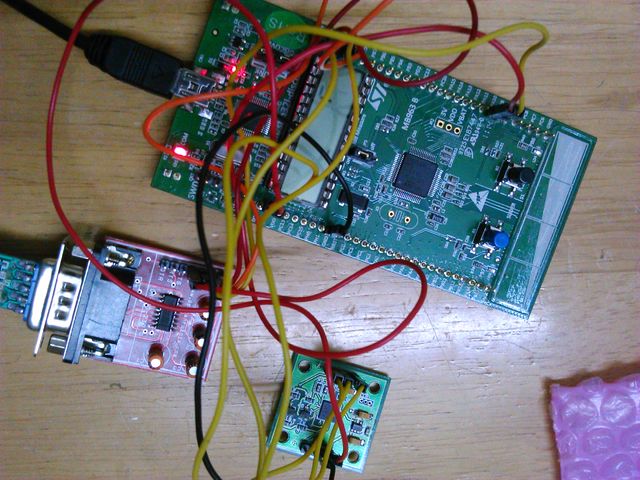
BLOCK DIAGRAM
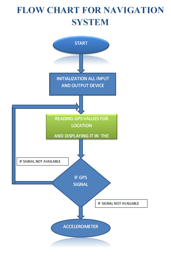
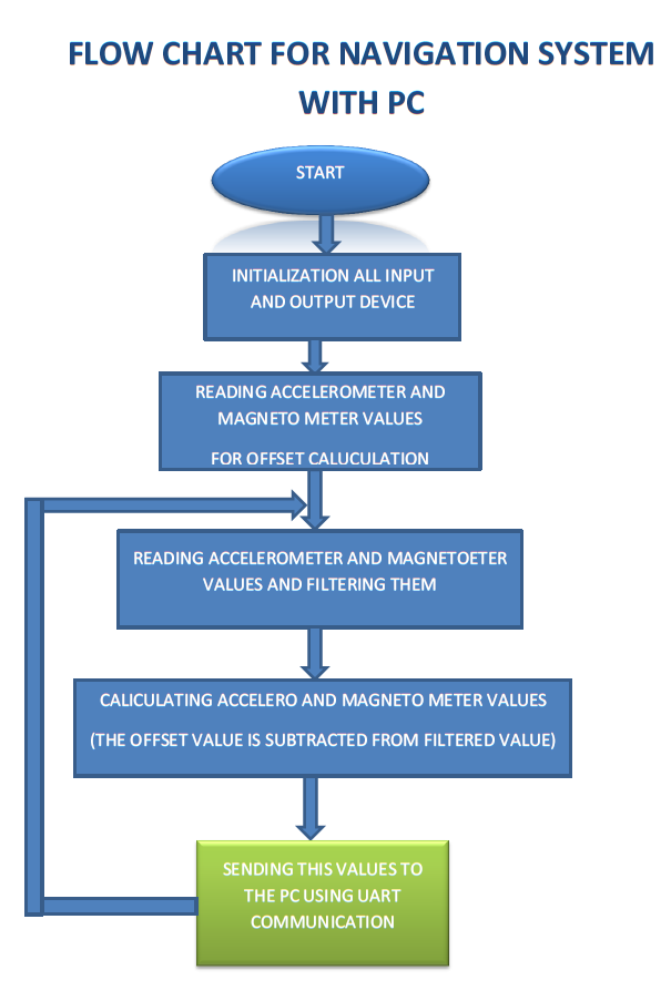
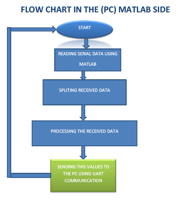
FLOW CHART
ACCELEROMETER CONFIGURATION
The Accelerometer LIS3LV02DL is connected to I2C bus as slave. STM32F103x is master on I2C bus. The GPIO pins PB10 and PB11 (I2C2) are configured in open drain alternate function mode. Also, for required application of position computations, the Control registers of accelerometer module is configured as follows. The detailed description of registers can be found in the datasheet of LIS3LV02DL.
SLAVE ADDRESS = 0x3A
CTRL_REG1 (20h)
![]()
we have configured it as 0xC7, which implies all three axis are enabled, decimation factor of 512 corresponding to 40Hz data rate.
CTRL_REG2 (21h)
![]()
we have configured it as 0x44, which implies no output registers updates while reading, enables the data ready generation and acceleration range as +/- 2g. Also, output data registers are represented in 12 bit right justified mode (2’s complement)i.e for +/- 2g, maximum count would be +/-2048.
CTRL_REG3 (22h)
![]()
we have configured it as 0x10, which implies internal filter is used and filter coefficient(Hpc) = 512.
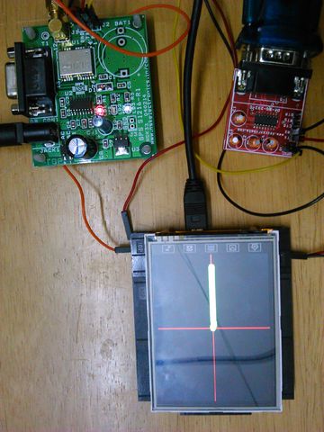
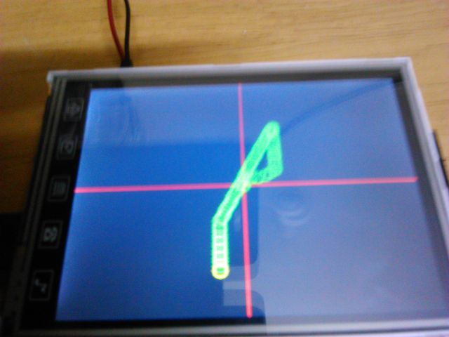
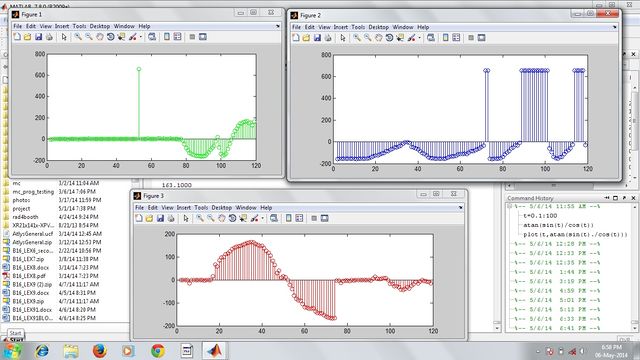
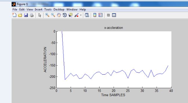
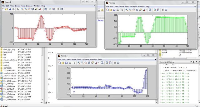
RESULTS
CONCLUSION
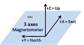
The Digital Level Sensor and Position detection algorithm using 3-axis accelerometer has been successfully demonstrated. The position algorithm can be directly used with slight sensitivity modification for PC mouse application. However, the algorithm can be further improvised for navigation with the use of magnetometer for north reference. The position error due module tilt with respect to local vertical can be compensated with use of 3-axis gyroscope (orientation sensor).
REFERENCE
1. Application Note- Implementing Positioning Algorithms Using
2. Data Sheet STM32F- Datasheet-stm32f103
3. Olimax LCD- STM32_LCD-data
PROJECT TEAM
PERUMALLA GOPI RAGHAVENDRA
SAMBASIVA RAO
Recent Comments